

 En
En



How to Control a Coreless Linear Motor?
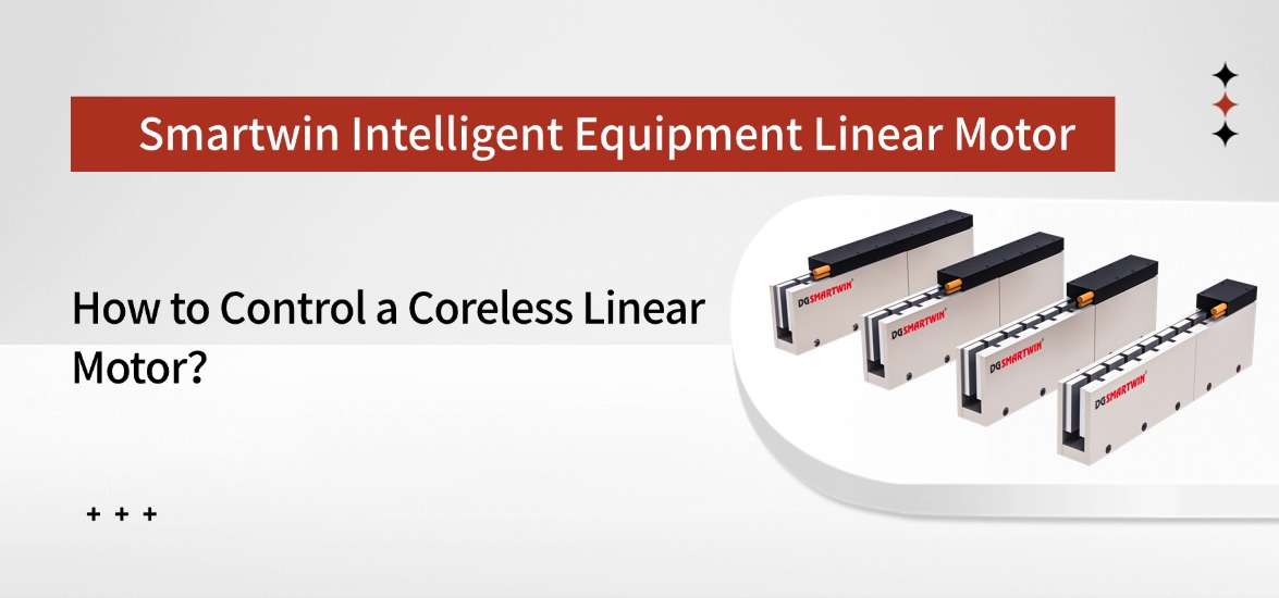
This article explains the key control principles and the most common issues engineers need to consider when integrating a coreless linear motor.
1. What Makes Coreless Linear Motor Control Different?
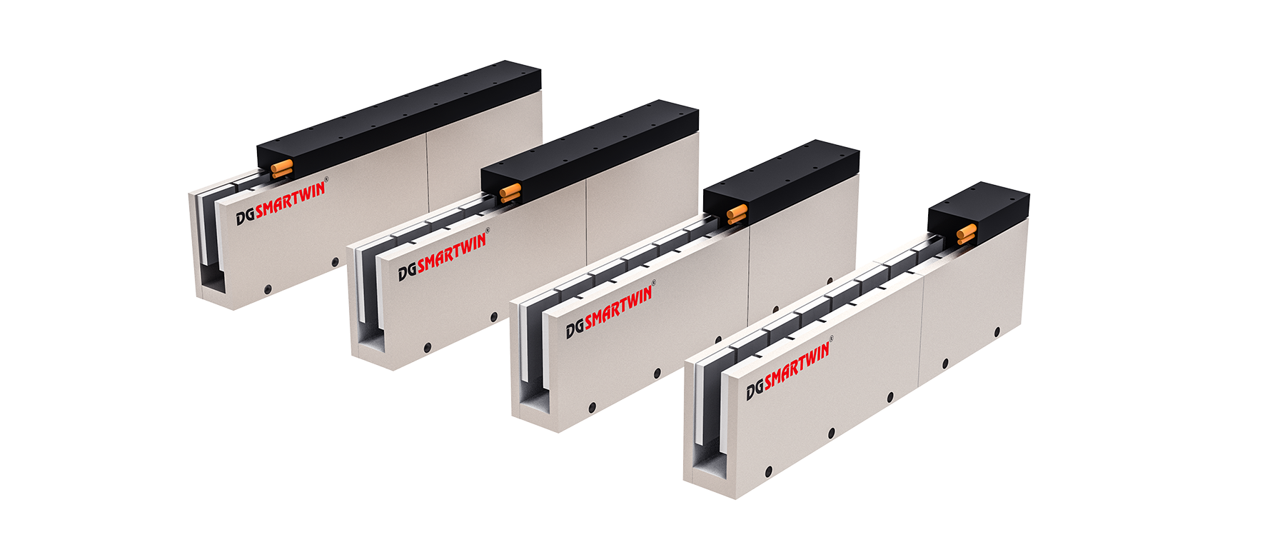
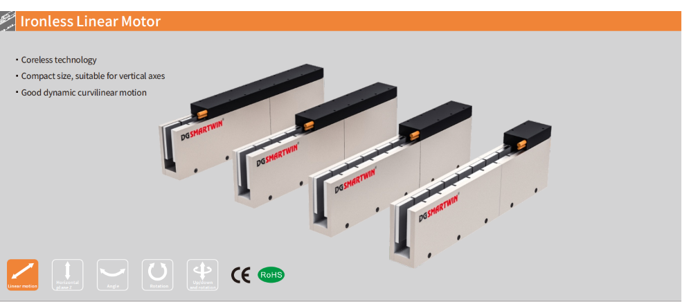
A coreless linear motor uses a lightweight coil without an iron core. This design produces almost no cogging force and eliminates magnetic attraction between the coil and the magnet track. As a result, the motor provides smooth motion, rapid response, and direct force transmission.
Low Inertia and Rapid Response
The lightweight moving coil gives the motor low inertia, allowing it to follow changes in position, speed, and acceleration commands quickly.
This characteristic makes coreless linear motors suitable for high-speed scanning, rapid positioning, optical alignment, automated inspection, and precision measurement. Because the stage responds quickly, servo gains and acceleration parameters must be set carefully to avoid vibration or overshoot.
Smooth Motion at Low Speed
The absence of cogging allows the stage to move smoothly even at low operating speeds. This is particularly important in applications that require stable scanning, fine positioning, or consistent velocity.
Low-speed performance is also influenced by encoder resolution, guide friction, mechanical stiffness, and control-loop tuning. The motor structure provides the foundation, while the complete system determines the final motion quality.
No Magnetic Attraction
Unlike an iron-core linear motor, a coreless design does not generate attraction force toward the magnet track. This reduces the vertical load applied to the linear guides and bearings.
Lower guide loading can reduce friction, simplify alignment, and support smoother movement. For this reason, coreless linear motors are often used in lightweight stages and high-precision positioning platforms.
Direct-Drive Load Control
A coreless linear motor transfers force directly to the moving load without ball screws, belts, gears, or other transmission components. This removes backlash and reduces errors caused by mechanical clearance or wear.
However, direct drive also means that the servo system must control the full moving mass without assistance from gear reduction or transmission damping. Motor sizing, stage rigidity, and control parameters therefore have a direct influence on positioning stability.
2. Key Components: Driver, Encoder, and Controller
A complete coreless linear motor system normally includes three main control components: the servo driver, the position encoder, and the motion controller.
Component | Main Function | Key Selection Factors |
Servo Driver | Regulates motor current and controls the thrust generated by the coreless linear motor. | Continuous and peak current, DC bus voltage, commutation method, encoder interface, control bandwidth, and protection functions. |
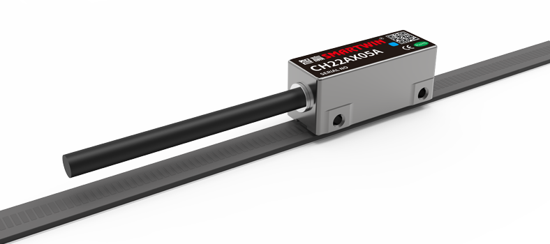
Linear Encoder | Measures the actual position of the moving stage and provides feedback for closed-loop control. | Resolution, travel length, maximum speed, signal type, installation accuracy, environmental conditions, and mounting tolerance. |
Motion Controller | Generates position, velocity, acceleration, and motion-profile commands for the servo system. | Axis count, interpolation capability, synchronization functions, control cycle, and support for trapezoidal or S-curve profiles. |
Servo Driver
The servo driver controls the current supplied to the coreless linear motor. Since motor thrust is directly related to current, the driver determines how much force is produced during acceleration, constant-speed motion, deceleration, and positioning.
It receives motion commands from the controller and converts them into electrical output for the motor coil. Stable current regulation helps the low-inertia moving coil respond quickly while reducing vibration, overshoot, and unstable motion.
Linear Encoder
The linear encoder measures the actual position and movement of the stage. The encoder provides the primary position feedback for the control system.
The measured position is continuously compared with the commanded position. When an error occurs, the system adjusts the motor output in real time, helping maintain accurate positioning, smooth low-speed motion, and consistent velocity.
Motion Controller
The motion controller defines how the coreless linear motor should move. It generates commands for target position, speed, acceleration, deceleration, and the overall motion sequence.
The controller coordinates the servo driver and encoder throughout the movement. It sends the required motion command, receives actual position feedback, and calculates the correction needed to keep the stage on the planned trajectory.
Together, the motion controller, servo driver, and linear encoder form the closed-loop control system of a coreless linear motor. The controller defines the movement, the driver generates the required thrust, and the encoder confirms the actual stage position.
3. How Closed-Loop Control Improves Coreless Linear Motor Accuracy
In a coreless linear motor control system, the encoder measures the actual stage position and sends the data back to the servo system. The controller compares this position with the commanded value, and the difference is referred to as position error or following error.
Based on this error, the servo driver adjusts the motor current and changes the generated thrust. This continuous correction allows the stage to follow the programmed position, speed, and trajectory more closely.
Real-Time Position Correction
Position feedback is updated continuously while the stage is moving. When the actual motion begins to deviate from the command, the servo system immediately increases or reduces the motor output.
This response is particularly effective with a coreless linear motor because its lightweight coil has low inertia. Small current adjustments can quickly influence stage movement, helping the system correct errors before they become significant.
Three Nested Control Loops
Most servo systems use current, velocity, and position loops to manage different stages of motion.
The current loop regulates motor current and therefore controls linear thrust. It operates at the highest response speed because force must change quickly during acceleration, deceleration, and disturbance correction.
The velocity loop maintains the required stage speed by adjusting the thrust command. The position loop compares commanded and measured positions, then calculates the correction needed to reach and settle at the target.
By coordinating force, speed, and position, the three loops allow the stage to follow the planned motion more accurately.
Response to Load and External Disturbances
Changes in payload, guide friction, cable resistance, or external process force can cause the stage to move away from its intended trajectory.
When the moving load increases, for example, the stage may briefly fall behind the command. The encoder detects the deviation, and the control system raises the motor current to generate additional thrust.
This feedback mechanism helps maintain stable motion when operating conditions change, rather than relying on a fixed motor output.
Motion Accuracy and Stability
A well-tuned closed-loop system improves positioning repeatability, velocity consistency, trajectory tracking, and settling behavior. It also makes the stage less sensitive to moderate variations in load and friction.
For coreless linear motors, closed-loop control is especially important because direct drive removes the mechanical reduction and damping provided by screws, belts, or gear systems. Motion accuracy therefore depends heavily on the quality of feedback and correction.
Servo Gain Adjustment
Servo gain determines how strongly the system reacts to a detected motion error.
Low gain settings may result in slow response, larger following errors, and longer settling times. Excessively high gains can make the stage oscillate, overshoot the target, or generate mechanical noise.
Tuning should begin with moderate settings and increase gradually. Following error, vibration, motor current, and settling time should be observed throughout the process to identify a stable balance between response speed and motion smoothness.
Feedforward Control
Feedforward control improves tracking by estimating the output required before a noticeable position error occurs.
Velocity feedforward supports consistent movement at the commanded speed, while acceleration feedforward supplies additional force when the stage accelerates or decelerates. This reduces the amount of correction required from the feedback loops.
Feedforward should be introduced only after the basic servo loops are stable. When properly configured, it can reduce tracking delay and improve dynamic performance without making the system overly sensitive.
4. Common Coreless Linear Motor Control Challenges and SMARTWIN Solutions
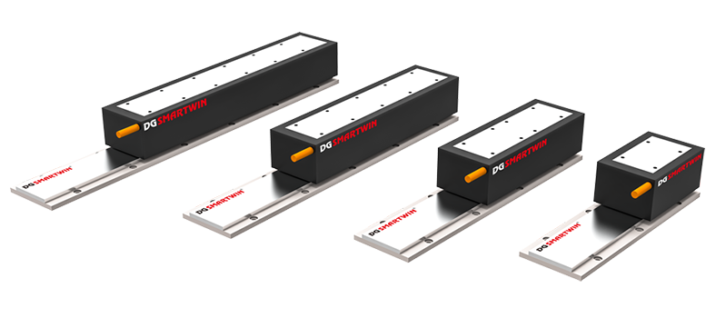
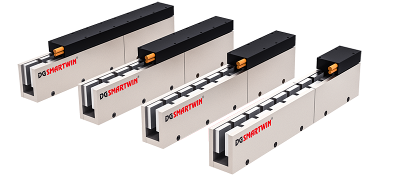
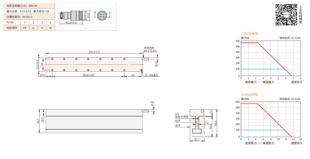
SMARTWIN CUM series coreless linear motors feature a direct-drive, ironless structure with no cogging force and operating speeds of up to 5 m/s. Their low-inertia coil supports fast and smooth motion, but actual system performance still depends on stage rigidity, encoder feedback, servo tuning, and the complete operating cycle.
Motor Vibration or Oscillation
Vibration in a coreless linear motor system is usually caused by servo settings, structural resonance, encoder disturbance, or uneven mechanical resistance. Since the CUM series has no cogging force, repeated vibration should not immediately be attributed to the motor structure itself.

The timing of the vibration often reveals the cause. Jitter at standstill may indicate excessive position gain, encoder noise, or loose mounting. Oscillation during acceleration is more likely to result from high jerk or insufficient frame stiffness. Vibration within a narrow speed range usually suggests a structural resonance frequency.
Start by checking the coil mounting, magnet track alignment, guide rails, encoder bracket, load connection, and cable chain. The cable chain should apply similar resistance in both travel directions. After confirming the mechanical condition, adjust position gain, velocity gain, acceleration, and jerk gradually. Notch or low-pass filters should only be introduced when the resonance source has been identified.
Position Overshoot
Position overshoot occurs when the stage moves beyond the target before returning to the commanded position. This is more noticeable in coreless linear motor systems because the lightweight coil responds quickly and the direct-drive structure does not provide additional damping from a screw or gearbox.
The commanded position, actual position, velocity, and current curves should be reviewed together. A sharp current peak near the end of the move may indicate excessive deceleration. Repeated movement around the target normally points to high servo gain, insufficient damping, or unsuitable feedforward settings.
Using an S-curve profile can reduce sudden changes in acceleration and jerk. Deceleration, velocity-loop response, position-loop gain, and feedforward should be coordinated rather than reducing the overall speed alone.
Excessive Following Error
Following error is the difference between the commanded position and the actual encoder position. The stage of motion at which the error appears can help narrow down the cause.
An error that increases mainly during acceleration may indicate insufficient peak thrust or driver current limitation. If the error continues during constant-speed travel, check guide friction, cable drag, voltage limitations, and speed settings. Irregular error spikes are more likely to result from encoder signal interruption, scaling errors, or unstable feedback.
The required motor force should include moving mass, acceleration, guide resistance, and any external process load. The CUM2 series provides 25.5–51 N of continuous thrust, while the CUM7 series provides 205.5–411 N. Peak thrust across the series ranges from 127.6 N to 2959.2 N, allowing the system to be matched to both short acceleration demands and continuous operating loads.
Motor Overheating
Motor temperature is influenced by RMS current, acceleration frequency, duty cycle, ambient temperature, and heat dissipation. Frequent short moves can still produce significant heat when the coil repeatedly operates near peak force.
Current should be monitored across the full machine cycle rather than during a single movement. Repeated high current during acceleration and deceleration may indicate an overly aggressive motion profile. High current while the stage is stationary may be caused by stage imbalance, guide friction, an external holding force, or continuous servo correction.
Temperature rise can be reduced by lowering acceleration and jerk, extending the move time, reducing cycle frequency, improving heat transfer, and removing unnecessary mechanical resistance. SMARTWIN CUM configurations can also include a temperature sensor for direct coil-temperature monitoring during continuous operation.
Encoder Noise or Position Instability
Encoder-related faults may appear as standstill jitter, unstable low-speed movement, sudden position-count changes, servo noise, or following-error alarms. The low inertia of a coreless linear motor makes these disturbances easier to observe because the coil reacts quickly to feedback fluctuations.
Encoder cables should be separated from motor power cables and other high-current wiring. Shielding, grounding, connectors, signal interpolation, position scaling, and readhead mounting should be inspected carefully. The encoder must remain aligned with the scale across the entire travel range, not only near the home position.
Feedback polarity should be verified before normal commissioning. If encoder direction is opposite to the motor command, the servo system may increase the error instead of correcting it. Initial testing should therefore use limited current, low speed, restricted travel, active limit switches, and an accessible emergency stop.
For faster troubleshooting, the key operating data should include the CUM motor model, moving mass, travel length, maximum speed, acceleration, duty cycle, encoder type, driver model, following-error curve, current profile, and coil temperature. These records help determine whether the fault comes from the mechanical structure, feedback signal, servo tuning, thrust capacity, or thermal load.
Conclusion
Reliable coreless linear motor control depends on more than the motor itself. The servo driver must regulate thrust accurately, the encoder must provide stable position feedback, and the motion controller must generate suitable speed, acceleration, and positioning commands.
Contact SMARTWIN with your payload, travel, speed, acceleration, and operating-cycle requirements for application-based technical support.
Read more:
https://www.zhiyingmotor.com/articledetail/how-to-choose-an-efficient-direct-drive-linear-motor.html
FAQs About Coreless Linear Motor
1. Does a coreless linear motor require a servo driver?
A coreless linear motor normally requires a servo driver because its thrust is controlled directly by coil current. The driver converts motion commands into regulated current for acceleration, constant-speed movement, deceleration, and positioning. Stable current control is essential for maintaining smooth motion and preventing sudden force changes.
2. Can a coreless linear motor operate without an encoder?
A coreless linear motor can move without an encoder, but accurate positioning requires closed-loop feedback. The encoder measures the actual stage position and sends this data to the controller, allowing the system to correct position and velocity errors in real time. Open-loop operation is generally unsuitable for applications that require repeatable and precise motion.
3. Why can a coreless linear motor vibrate even though it has no cogging force?
A coreless linear motor can still vibrate because most oscillation comes from servo tuning, encoder noise, structural resonance, or uneven mechanical resistance rather than cogging force. Jitter at standstill often indicates excessive position gain or unstable feedback, while vibration within a specific speed range usually points to mechanical resonance. The mounting structure, guide rails, encoder bracket, and cable chain should be checked before adjusting gains or filters.
4. How can position overshoot be reduced in a coreless linear motor system?
Position overshoot is reduced by coordinating servo gain, deceleration, feedforward, and the motion profile. An S-curve profile smooths changes in acceleration and jerk, helping the stage approach the target with less mechanical shock. Position, velocity, and current curves should be reviewed together to determine whether the overshoot is caused by aggressive commands or insufficient damping.
5. What causes excessive following error in a coreless linear motor?
Excessive following error occurs when the actual stage position cannot keep up with the commanded position. Common causes include insufficient thrust, driver current limitation, excessive acceleration, guide friction, cable drag, incorrect encoder scaling, or unstable feedback. The point at which the error appears during the motion cycle often helps identify the source of the problem.
6. How can a coreless linear motor be protected from overheating?
A coreless linear motor can be protected from overheating by controlling RMS current, acceleration frequency, duty cycle, and heat dissipation. Frequent short moves may still generate significant heat when the coil repeatedly operates near peak thrust. Monitoring current and coil temperature across the complete machine cycle provides a more reliable assessment than checking a single movement.
7. Why is closed-loop control important for a coreless linear motor?
Closed-loop control improves accuracy by continuously comparing the commanded position with the actual encoder position. The servo system uses the resulting position error to adjust motor current and correct the stage movement in real time. This process improves positioning repeatability, velocity stability, trajectory tracking, and settling performance.
8. What data is needed to troubleshoot a coreless linear motor system?
Effective troubleshooting requires the motor model, moving mass, travel length, maximum speed, acceleration, duty cycle, encoder type, driver model, and servo settings. Following-error curves, motor-current profiles, and coil-temperature records are also useful. These data points help determine whether the problem comes from mechanical resistance, feedback signals, servo tuning, thrust capacity, or thermal load.
Back To List