


 En
En

How to Choose an Efficient Direct Drive Linear Motor?
This guide explains the key principles behind efficient direct drive linear motor selection, including force matching, motion performance, control system integration, and system-level design considerations.
1.What Makes a Direct Drive Linear Motor Efficient
Efficiency in a direct drive linear motor is not defined only by energy consumption, but by how reliably and consistently the system performs under real operating conditions.
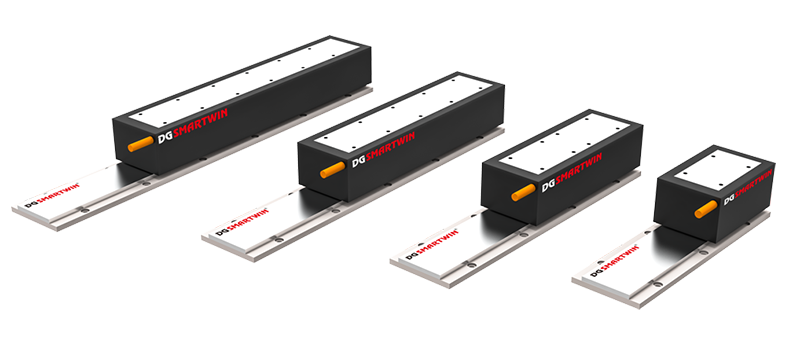
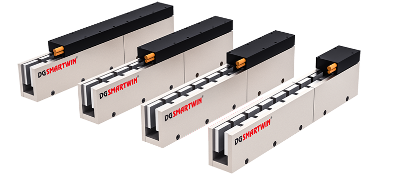
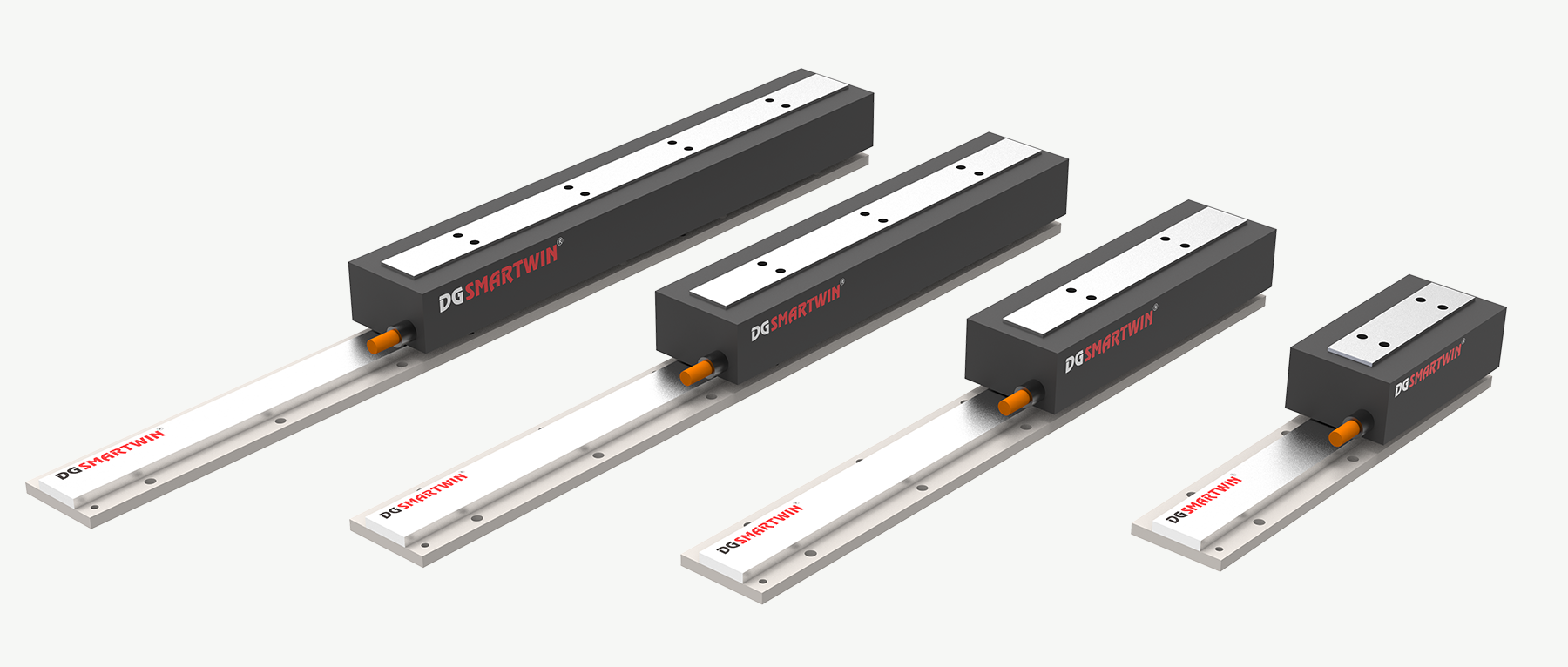
One of the key factors is positioning feedback accuracy. In Smartwin’s CFS series linear motors, armature width options range from 35mm to 125mm, while modular armature lengths extend from 87.1mm up to 411.1mm, allowing flexible configuration to match different machine structures and integration requirements.
This level of structural flexibility has a direct impact on overall system efficiency. When the motor is properly matched to the application, it reduces unnecessary mechanical compensation, improves control stability, and supports more consistent closed-loop performance, especially in high-precision motion systems.

2.Matching Motor Force in Direct Drive Linear Motor Selection
Motor force should be defined by actual motion behavior in the application, rather than being estimated only from static load assumptions.
Within Smartwin’s CFS series, different configurations are aligned with distinct mechanical requirements. The CFS-035 is typically used in space-constrained systems where compact structure is the priority. The CFS-045 is more suitable for general-purpose automation, where load and stroke need to be balanced. For higher-demand conditions, the CFS-065 provides improved rigidity and stronger output support for heavier motion profiles.
To accommodate different machine designs, the series also offers armature length variations from 87.1mm (A type) up to 411.1mm (F type), enabling adjustments in structural layout and motion range without changing the core system architecture.
This range of configurations allows engineers to align motor selection more closely with real operating conditions, ensuring force output is neither excessive nor insufficient, but appropriately matched to the application demand.

3.Check Speed, Acceleration, and Duty Cycle
Speed and acceleration should be evaluated as part of the overall motion system, considering thrust capability, load conditions, and mechanical structure, rather than being treated as standalone specifications.
In Smartwin’s CFS series linear motors, dynamic performance scales with armature configuration. Different structural lengths directly influence available continuous and peak thrust, which in turn affects acceleration behavior and motion stability.
CFS Series Performance Overview
Model | Armature Length | Continuous Thrust | Peak Thrust | Application Focus |
CFS035A | 87.1 mm | 24 N | 53 N | Compact, high-speed positioning |
CFS045A | 87.1 mm | 48 N | 113 N | General automation, balanced load |
CFS065A | 87.1 mm | 96 N | 226 N | High-response compact systems |
CFS045F | 411.1 mm | 289 N | 677 N | Medium-heavy load applications |
CFS065C | 216.7 mm | 289 N | 677 N | Balanced performance systems |
CFS065F | 411.4 mm | 577 N | 1355 N | Heavy load, long stroke systems |
Across the platform, armature lengths from 87.1 mm to 411.4 mm provide scalable motion design flexibility, allowing engineers to balance thrust output, inertia, and stroke requirements within a unified system architecture.

In real industrial environments such as SMT production and semiconductor equipment, duty cycle becomes a key design constraint. Higher thrust configurations naturally introduce higher thermal load during repeated acceleration and deceleration cycles, making system-level thermal management essential for stable long-term operation.
4.Drive, Encoder, and Control Matching for Efficient Direct Drive Linear Motor Performance
A direct drive linear motor system does not rely on the motor alone. Its performance depends largely on how well the drive, encoder, and control system are integrated as a unified motion architecture.
In Smartwin’s CFS platform, different winding configurations are designed to ensure compatibility with a variety of drive systems, helping maintain stable output behavior and consistent response across different control conditions.

Meanwhile, encoder-based closed-loop control plays an essential role in maintaining positioning accuracy under different system configurations and load variations. This ensures stable motion performance even when operating across different motor models within the same platform.
When the drive response, feedback accuracy, and motor structure are properly aligned, the system achieves smoother motion behavior, improved stability, and higher overall efficiency.
5.Avoid Oversizing and Poor System Integration
One of the most common causes of inefficiency in linear motor applications is selecting a configuration that exceeds actual system requirements.
An oversized setup can introduce unnecessary inertia, reduce responsiveness under light load conditions, and increase system cost without delivering proportional performance benefits.
Beyond motor selection itself, mechanical integration also plays an equally important role. The armature structure must be aligned with machine stiffness, installation accuracy, and vibration control requirements. If these factors are not properly balanced, even a correctly selected motor may experience reduced positioning stability or unwanted vibration during operation.

Conclusion
By aligning motor selection with actual application conditions, engineers can avoid common issues such as oversizing, instability, and inefficient system integration. Smartwin’s CFS series provides a scalable platform that supports this approach, helping achieve more reliable performance across different industrial automation scenarios.
For application support or system selection guidance,contact Smartwin’s engineering team to evaluate the most suitable CFS configuration for your motion requirements.
Read more:
Back To List