

 En



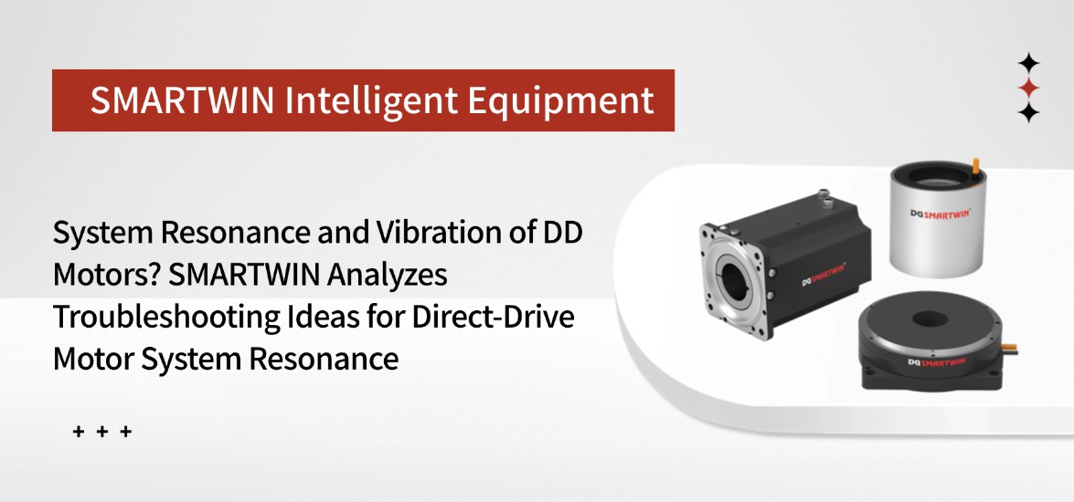
Resonance & Vibration of Complete DD Motor Assembly? SMARTWIN Explains Resonance Troubleshooting for Direct-Drive Motor Systems
Resonance & Vibration of Complete DD Motor Assembly? SMARTWIN Explains Resonance Troubleshooting for Direct-Drive Motor Systems
Resonance is a frequent and often misdiagnosed issue for direct-drive motors used in rotary stations for 3C placement and laser processing.
Typical symptoms: Static positioning specifications and repeat positioning performance pass inspection, yet obvious vibration occurs when the rotational speed sweeps across a certain range. Such vibration directly compromises the process, resulting in placement offset and periodic defects on laser patterns.
On-site engineers usually start by tuning the drive PID parameters. However, increasing the gain amplifies vibration, while reducing the gain slows positioning response and fails to meet cycle-time and precision requirements. This dilemma arises because the resonance source is not within the controller; it originates from the full mechanical system consisting of the motor, load and mounting structure.
A key understanding should be established first: resonance can hardly be eliminated completely by parameter tuning alone. Two mainstream on-site approaches are available. The first is to optimize mechanical system characteristics to shift the resonant frequency outside the operating speed range used in production processes. The second is to apply filtering to suppress vibration amplitude within acceptable process limits. Our target is controllable resonance rather than total elimination of resonance. This principle defines the sequence of the whole troubleshooting workflow.
I. Mismatch Between Load and Motor, Causing Natural Frequency to Fall Within Operating Range
If only rated torque is checked during equipment selection while inertia matching is ignored, the ratio of load inertia to motor inertia will become excessive. Consequently, the natural frequency of the entire rotary system falls into the actual operating speed range, triggering resonance during operation.
1. Unbalanced load inertia ratio makes the system natural frequency coincide with the working speed band.
2. Increasing drive gain aggravates vibration; reducing gain slows positioning response and fails process requirements.
3. Only torque values from datasheets are reviewed without inertia simulation, so the problem is uncovered only during prototype commissioning.
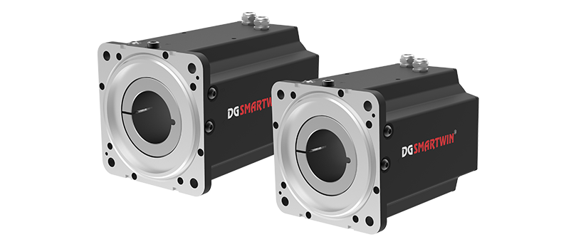
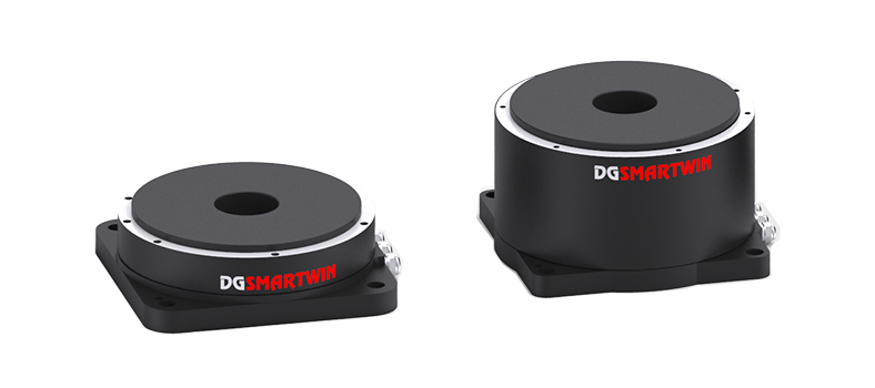
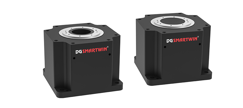
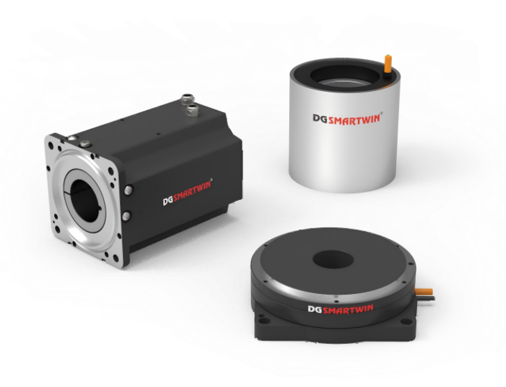
At the selection stage, SMARTWIN calculates not only torque but also verifies load inertia to check the rationality of inertia ratio. DGSMARTWIN DD motors provide multiple rotor inertia options. We select the proper model according to load conditions to keep the system natural frequency away from the production speed range and reduce the risk of resonance excitation.
II. Insufficient Rigidity of Mounting Base and Tooling Fixtures Amplifies Vibration Amplitude
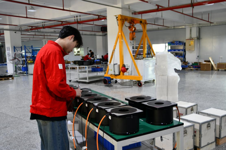
Even if the motor itself performs properly, minor vibration output from the DD motor will be amplified by weak structures when the mounting base, adapter flange or stage tooling lacks sufficient rigidity, which appears as obvious vibration of the whole machine. Many equipment manufacturers focus entirely on motor parameters while ignoring the structural design of adapters and bases. SMARTWIN technical support provides rigidity reference suggestions for motor mounting flanges and bases at the early project stage. We remind equipment builders to pay attention to adapter plate thickness and stiffener layout, so as to avoid the scenario where the motor itself is fine yet resonance is amplified by tooling and base structures.
III. Drive Control Algorithm Matching — Suppress Residual Vibration Together with Hardware Improvements
SMARTWIN’ s supporting AKS series drives are independently developed and equipped with filtering, notch filtering and other functions. For equipment with fixed hardware configuration, the notch frequency can be set inside the drive to suppress resonance at specific frequency bands and reduce on-site vibration. It should be noted that drive algorithms serve only as auxiliary suppression methods and cannot replace inertia matching and base rigidity design on the hardware side. When resonance occurs, inspect the mechanical system first before tuning drive parameters.
FAQ
Q: How to quickly distinguish structural resonance from external disturbance for a DD motor?
A: Perform continuous speed sweep testing and check the correlation between vibration frequency and rotational speed. If the vibration frequency stays constant and does not change with speed, the fixed natural frequency of the structure is excited — this is structural resonance. If the vibration frequency rises synchronously as speed increases, the excitation source is linked to rotary motion, indicating rotary disturbance (such as rotor unbalance, cogging force ripple, periodic dragging from cable chains or harnesses, etc.).
Q: Is a smaller inertia ratio always better?
A: No. The inertia ratio describes the relationship between motor inertia and load inertia. When the inertia ratio is relatively high, the motor rotor inertia delivers a flywheel effect and suppresses position fluctuation caused by external disturbances. Blindly pursuing an extremely low inertia ratio makes the system more sensitive to external forces, leading to larger acceleration deviation under the same disturbance. There is no universal optimum value for inertia matching. A suitable range shall be determined according to load characteristics (pure inertial point-to-point load or load with continuous disturbance force), process dynamic response and stability requirements. A low inertia ratio alone should not be the target.