

 En
En



Where Does the CFS045 Linear Motor Fit Best in Precision Automation?
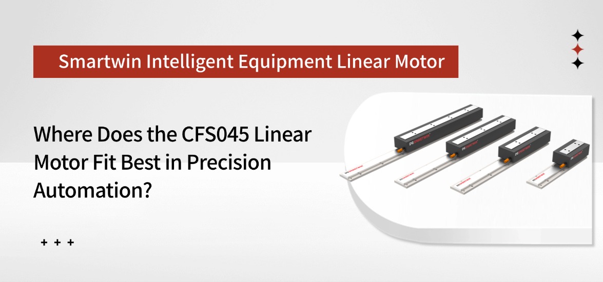
This guide looks at where the CFS045 fits best, how to evaluate it against a real motion cycle, and how to choose the right configuration for prototype testing.
What Is the CFS045 Iron Core Linear Motor?
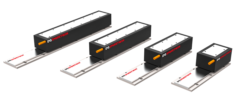
The CFS045 iron core linear motor is a compact direct-drive motor developed for automation axes that need a balance of force density, dynamic response, and stable motion.
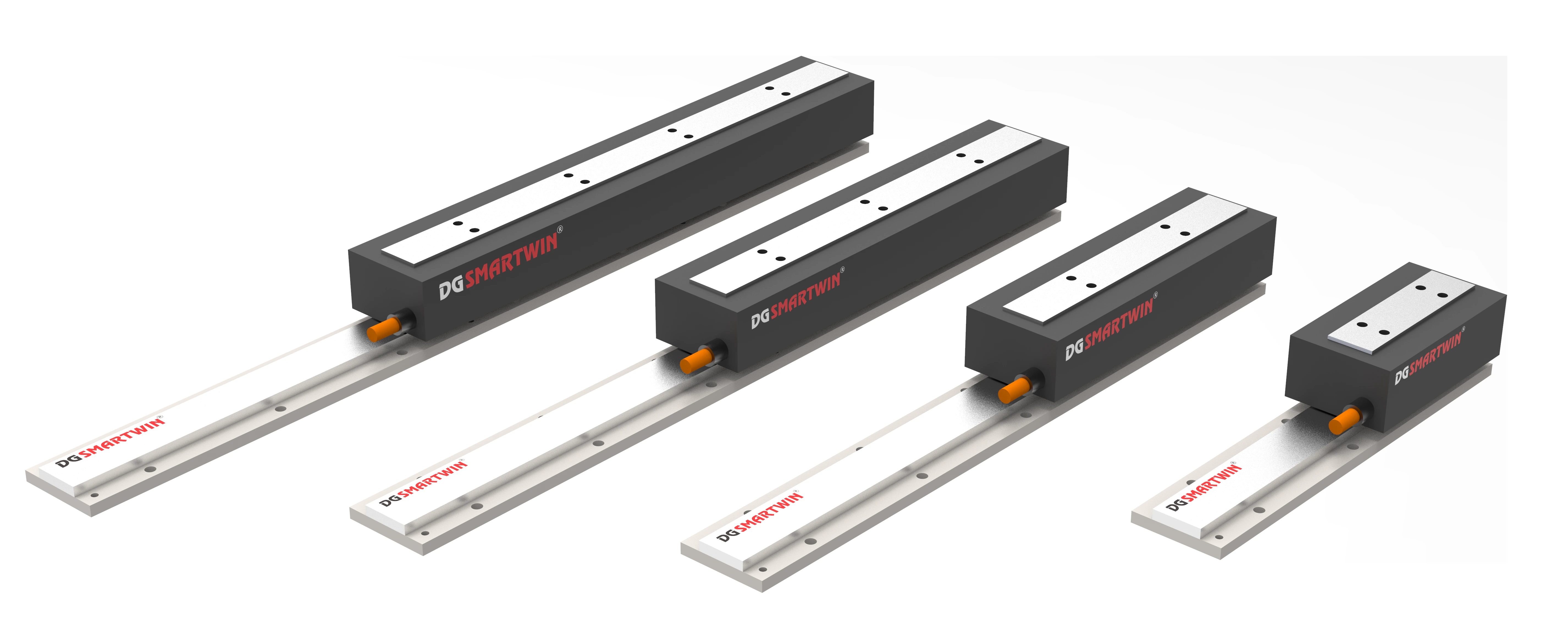
Its iron core structure allows the motor to deliver relatively high thrust within a narrow format. At the same time, the low-cogging design helps reduce force ripple during travel, which is useful when the axis needs smooth scanning, controlled low-speed movement, or clean settling at the target position.
The CFS045 family is available in six armature lengths rather than one fixed configuration.
That gives us more flexibility when the same machine platform has different payloads or acceleration targets. A lighter axis can use a shorter armature, while a higher-force version can stay within the same 45 mm motor family instead of switching immediately to a different platform.
This approach can also simplify mechanical design when several machine models share a similar axis structure.
Where Does the CFS045 Direct Drive Linear Motor Fit Best?
The CFS045 series runs from CFS045A to CFS045F.
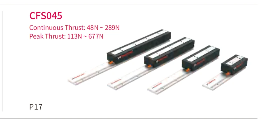
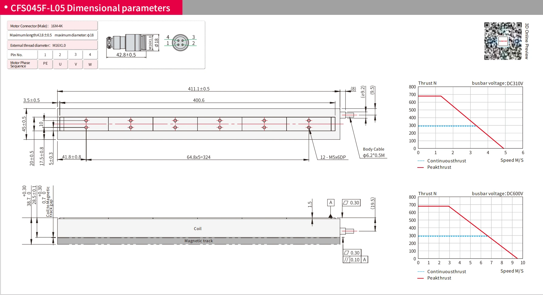
Armature length ranges from 87.1 mm to 411.1 mm. Continuous thrust covers 48 N to 289 N, while peak thrust ranges from 113 N to 677 N.
In practical machine design, the CFS045 direct drive linear motor fits best where the axis needs more than light-duty positioning force but does not justify a larger high-thrust motor platform.
1.Limited Space
The CFS045 uses a 45 mm armature width, which helps keep the motion axis relatively compact.
This is useful in equipment where linear guides, encoders, fixtures, sensors, and cable routing already compete for limited installation space.
When the force requirement increases, a longer CFS045 armature can be selected while keeping the same basic motor width.
For compact automation equipment, this gives the mechanical designer more freedom to increase thrust without making major changes to the overall axis layout.
2.Fast Indexing
Many automation axes spend most of the cycle accelerating, stopping, indexing, and reversing rather than running continuously at top speed.
In this type of motion, peak force and acceleration capability often matter more than maximum velocity.
The CFS045 is designed for high acceleration, making it suitable for short, repetitive point-to-point movements where cycle time is important.
The complete duty cycle still has to be checked. A motor may handle a short acceleration peak comfortably but build excessive heat if the same movement is repeated at a high frequency.
3.Smooth Motion
Some automation processes depend as much on motion quality as on speed.
Inspection stages, measurement systems, and precision positioning axes may need stable travel through a scan or a short settling time after each move.
The CFS045 uses a low-cogging design to reduce periodic force variation during movement.
This helps make the motor suitable for applications where smoother travel and controlled positioning are important alongside thrust and acceleration.
Precision Automation Tasks for the CFS045 Linear Motor
Industry labels do not always tell us whether a motor is suitable. The actual motion task is usually more useful.
Three types of precision automation tasks are especially relevant to the CFS045.
1.Indexing
A common example is a stage that moves a component between several fixed process positions.
The axis may pick up a part, accelerate toward the next station, stop for inspection or processing, and then continue to another position.
Here, the motor has to provide enough force for rapid acceleration while still allowing the stage to stop cleanly at the target.
For a lighter moving assembly, one of the shorter CFS045 versions may already be sufficient.
As fixture weight or required acceleration increases, a longer armature can provide more available thrust without changing the motor family.
This makes the CFS045 practical for machine platforms that use similar axis layouts across several load levels.
2.Scanning
Scanning and inspection stages operate differently from fast indexing axes.
A camera, sensor, or workpiece may move continuously through a defined path while data is collected.
During that part of the cycle, stable motion can be more important than aggressive acceleration.
Low cogging becomes valuable because force ripple can affect velocity consistency, especially during slower or controlled travel.
The final result still depends on the complete motion system. Linear guide quality, encoder resolution, structural rigidity, and servo tuning all contribute to the actual scanning performance.
3.Pick and Place
Pick-and-place motion often includes changing loads.
The stage may travel empty, pick up a component, move under load, stop for assembly or inspection, release the part, and then return.
The motor therefore sees different force requirements during different parts of the cycle.
Sizing only around the empty movement can underestimate what the axis actually needs.
With six available CFS045 thrust levels, we can compare the same load profile against several configurations and select a model that covers the loaded section without adding unnecessary motor size.
How to Evaluate CFS045 Linear Motor Performance in a Motion Cycle
A useful CFS045 selection starts with one complete machine cycle rather than a single catalog number.
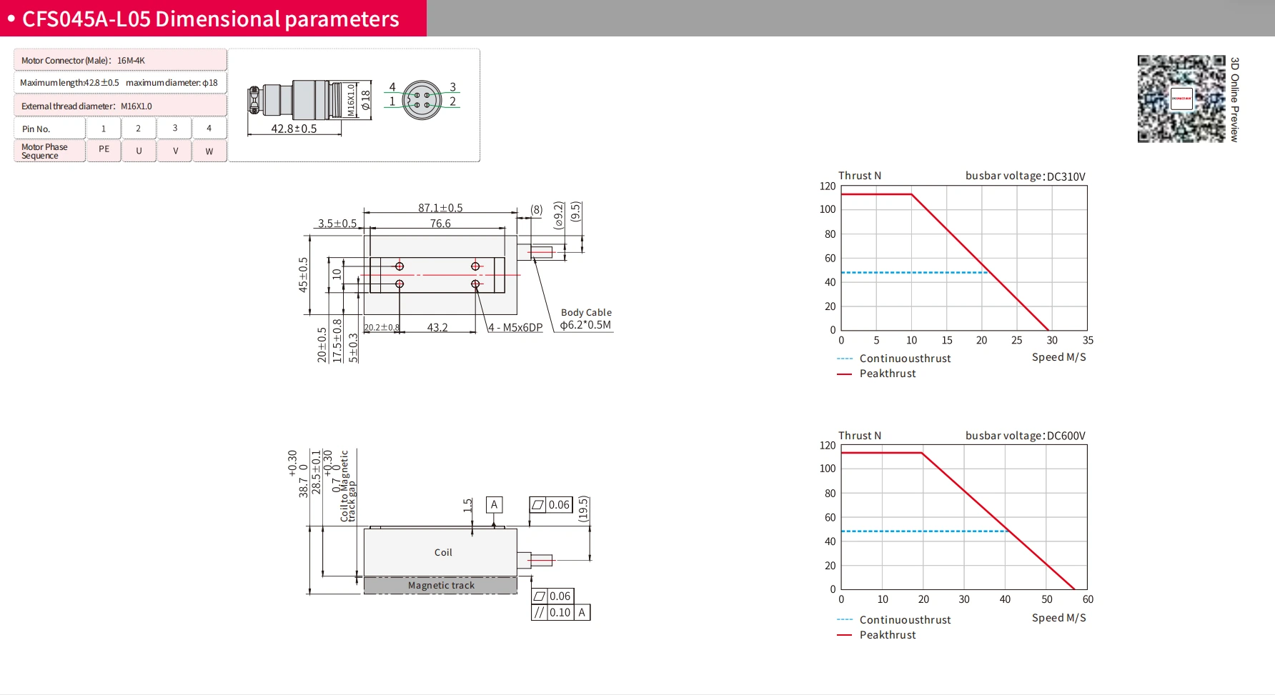
Suppose the stage begins at home, accelerates toward the working position, reaches the required travel speed, decelerates into the target, holds position during processing, and then returns.
Each part of that cycle places a different demand on the motor.
1.Peak Force
The acceleration phase usually creates the highest short-term force requirement.
That force is mainly affected by total moving mass, target acceleration, friction, and any external resistance from the process.
Across the CFS045 family, peak thrust ranges from 113 N to 677 N.
This gives us a direct reference for checking whether the selected model can handle the most demanding part of the movement.
Peak thrust alone, however, does not show whether the motor is correctly sized for continuous production.
2.Continuous Load
If the machine repeats the same cycle every few seconds, thermal load becomes just as important as peak force.
Acceleration, braking, constant-speed travel, holding time, and return motion all contribute to the effective force the motor experiences over one cycle.
A motor can look suitable when only peak thrust is considered and still run too hot once the full duty cycle is calculated.
For that reason, continuous thrust and RMS force should be checked together before the motor is finalized.
3.Travel Range
Travel length needs to be considered separately from motor thrust.
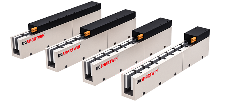
The CFS045 works with the MFS045 magnetic track family, including 128 mm and 192 mm stator sections.
These track sections can be arranged according to the required stroke.
A longer axis does not automatically need a longer CFS045 armature. Motor size is mainly determined by force and thermal demand, while travel distance is handled through the magnetic-track layout and the mechanical structure.
Separating these two decisions makes the selection process much clearer.
When Is the CFS045 Linear Motor Too Small?
The CFS045 covers a broad range of compact automation requirements, but it also has a clear upper limit.
There are several signs that a larger motor family should be evaluated instead.
1.High Continuous Force
The largest version, CFS045F, provides 289 N continuous thrust.
If the calculated RMS force is already close to this value, there is very little operating margin left.
That can become a problem if payload, cycle frequency, or acceleration increases later in development.
Running close to the continuous limit can also increase temperature rise during long production periods.
When the application sits near this boundary from the beginning, moving to a larger motor family is usually a better design choice.
2.High Peak Force
CFS045F provides up to 677 N peak thrust.
A short peak close to this value may be acceptable depending on the motion profile.
Repeated operation near the maximum is different.
Heavy fixtures, aggressive acceleration, gravity loads, or additional process forces can push the axis toward the top of the range on every cycle.
When this becomes normal operating behavior rather than an occasional condition, the CFS045 is already working with very little reserve.
3.Heavy Moving Load
Machine designs often become heavier as development continues.
Larger tooling, stronger fixtures, cable carriers, sensors, covers, and extra components can gradually increase the moving mass.
If every design revision pushes the motor selection further from CFS045B toward C, D, E, and finally F, it is worth reassessing the motor platform itself.
At some point, the axis may simply have moved into a heavier performance class.
In that situation, a larger motor can be a cleaner solution than continuing to increase armature length within the same 45 mm series.
4.Force Ripple Requirements
The CFS045 is an iron core motor with low cogging, but some applications place extremely strict limits on force ripple.
If the process depends on exceptionally smooth force output and force density is less important, an ironless linear motor may also be worth comparing.
The choice depends on the main priority of the axis.
For one machine, compact force density may matter most. For another, smoothness or minimum disturbance may carry more weight.
How to Select a CFS045 Linear Motor for Prototyping
Once the CFS045 family has been confirmed as a suitable platform, the next step is choosing the right armature size for prototype testing.
The selection should be based on the continuous thrust, peak thrust, moving load, acceleration requirement, and available installation space.
The largest motor is not automatically the best choice. A longer armature takes up more installation space and adds moving mass, so the prototype should use a configuration that provides enough force and thermal margin without unnecessary oversizing.
During prototype testing, we normally check acceleration, cycle time, temperature rise, settling behavior, and positioning performance under the actual motion cycle. If the selected model stays comfortably within the required range, it is suitable for further production validation.
Conclusion
The right configuration depends on the actual load, peak and continuous force, stroke, and duty cycle. By evaluating these factors together, engineers can select a CFS045 model with enough performance margin without unnecessary oversizing.

Smartwin can help evaluate your motion requirements and recommend a suitable CFS045 configuration for prototype and production applications.
FAQ About CFS045 Linear Motor
1.What applications are suitable for the CFS045 linear motor?
The CFS045 linear motor is suitable for compact precision automation applications that require fast acceleration, stable positioning, and moderate thrust output. It is commonly used for indexing stages, inspection systems, scanning equipment, and pick-and-place mechanisms where space and motion performance are important.
2.What is the difference between CFS045A and CFS045F?
The main difference between CFS045A and CFS045F is their thrust capability and armature length. CFS045A provides 48 N continuous thrust and 113 N peak thrust, while CFS045F provides up to 289 N continuous thrust and 677 N peak thrust for higher-load motion requirements.
3.How do I select the right CFS045 linear motor configuration?
The right CFS045 linear motor configuration is selected based on moving load, acceleration, stroke, duty cycle, and required thrust. A suitable model should provide enough force and thermal margin while avoiding unnecessary motor oversizing.
Back To List