

 En
En



Linear Encoder Accuracy: Understanding Resolution and Repeatability
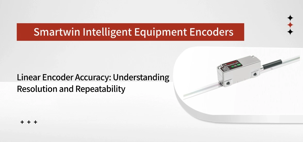
Choosing a linear encoder for precision motion systems requires more than comparing resolution values. Terms such as resolution, accuracy, and repeatability describe different aspects of encoder performance and directly affect how a machine achieves positioning results.
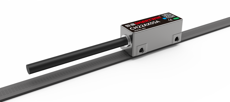
This guide explains how SH04 MC Type incremental optical encoder specifications should be interpreted, including the relationship between resolution and response speed, accuracy evaluation, controller compatibility, installation factors, and how to select the right configuration for different motion requirements.
Encoder Resolution in Motion Control
Encoder resolution is the movement represented by one output count. A smaller value divides the same travel distance into more counts, giving the controller finer position information.
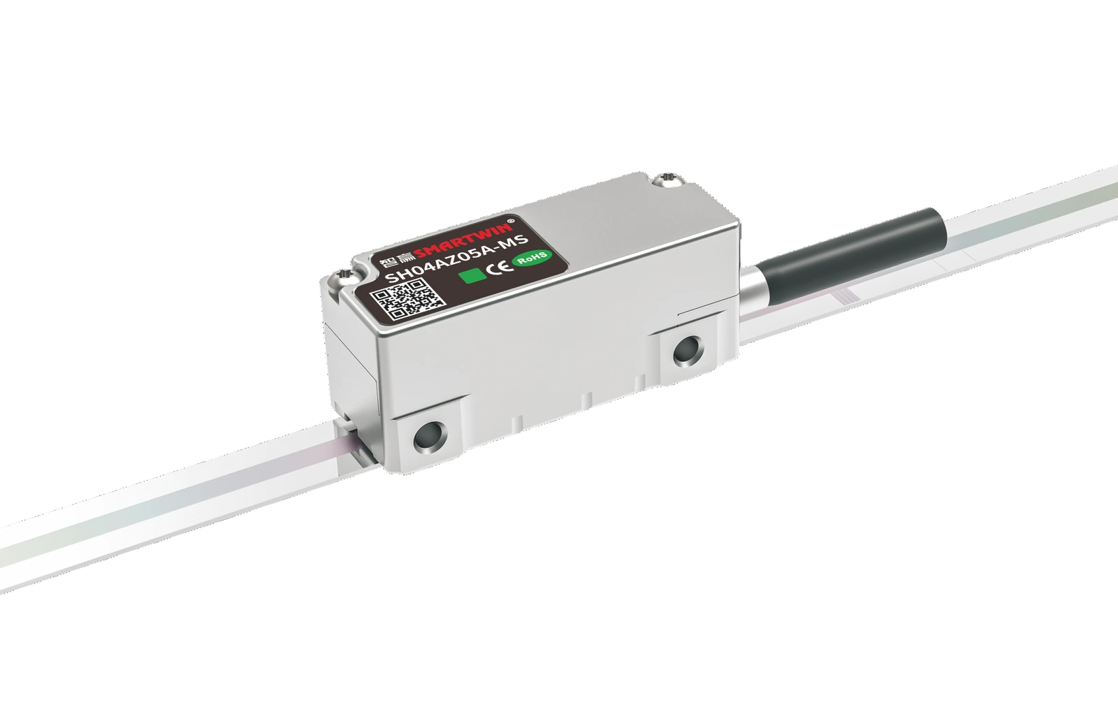
SH04 MC Type is an incremental optical encoder with a 40 μm grating pitch and ABZ differential output. Its resolution and maximum response speed are linked as follows:
The 0.1 μm setting provides ten times as many position counts as the 1.0 μm setting over the same travel. This can help a motion controller detect smaller position changes and make finer corrections during inspection, alignment, or precision positioning.
More counts also mean a higher signal frequency. At 0.9 m/s and 0.1 μm resolution, the approximate signal rate is:
Signal rate = 0.9 m/s ÷ 0.1 μm/count = 9,000,000 counts/s
At 3.2 m/s and 1.0 μm resolution:
Signal rate = 3.2 m/s ÷ 1.0 μm/count = 3,200,000 counts/s
The connected controller and servo drive must support the signal frequency generated at the selected speed. A finer setting may be unnecessary if the machine does not need such small feedback increments or if the controller cannot process the resulting frequency.
What Encoder Accuracy Really Means
Encoder accuracy describes the difference between the reported position and the actual physical position. SH04 MC Type has a stated positioning accuracy of ±2.5 μm/m, meaning that its permitted measurement deviation is defined within ±2.5 μm over one metre under the applicable conditions.
This value should not be interpreted as resolution. If the 0.1 μm configuration reports a movement of 1,000.000 mm, the finer output allows the controller to observe small changes within that travel, while the ±2.5 μm/m value defines how closely the overall reading corresponds to the actual distance.
A smaller output increment therefore improves measurement detail rather than automatically reducing absolute positional error. This is why changing from 1.0 μm to 0.1 μm resolution does not change the stated ±2.5 μm/m accuracy grade.
The machine’s final position may also differ from the encoder reading. Guideway error, mounting misalignment, structural deformation, vibration, and thermal movement can add error between the scale and the tool or workpiece. The encoder specification should therefore be treated as one part of the complete machine error budget.
Reading Linear Encoder Specifications
The SH04 MC Type specifications answer different engineering questions and should be reviewed as a complete set.
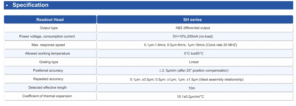
The 40 μm grating pitch is part of the optical measuring structure, not the final position increment received by the controller. Signal processing divides the optical period into the selected 1.0 μm, 0.5 μm, or 0.1 μm output.
The ABZ differential interface includes A and B position channels and a Z reference signal. Before selection, the servo drive or motion controller should be checked for interface compatibility and sufficient frequency capacity.
The operating temperature range also requires careful interpretation. A device may operate from 0–65°C, but the dimensional behaviour of the complete machine can still change across that range. Operating capability and positioning stability are related, but they are not the same specification.
What Affects Linear Encoder Repeatability
Repeatability shows whether an axis can return to the same position consistently. It does not show whether that position is absolutely correct.
An axis may repeatedly stop 2 μm away from the target with very little variation. In that case, the system has a stable offset and good repeatability. A consistent offset may be reduced through calibration, while irregular movement between cycles is harder to correct.
Direction reversal often reveals additional variation. When an axis approaches a target from opposite directions, backlash, friction, bearing movement, guide stability, and servo response can influence the stopping position.
The encoder only reports movement at its scale and readhead. Machine repeatability also includes the motor, guideways, bearings, structure, load, controller, and temperature. A feedback device can detect unwanted movement, but it cannot remove looseness, vibration, or structural deformation from the mechanics.
Repeatability should therefore be verified on the completed axis under realistic speed, direction, load, and cycle conditions. Measuring at the tool, camera, probe, or workpiece provides a more useful result than checking the feedback position alone.
Balancing Resolution and Response Speed
SH04 MC Type provides three configurations because a motion system rarely needs maximum resolution and maximum speed at the same time.
The 0.1 μm configuration offers the finest feedback and supports up to 0.9 m/s. It is suitable for slower inspection, alignment, and precision positioning tasks where small corrective movements are important.
The 1.0 μm configuration supports up to 3.2 m/s. It produces fewer counts over the same travel and is more suitable for fast transport, placement, and automation axes that do not require 0.1 μm increments.
The 0.5 μm option provides a middle point, combining finer feedback than the 1.0 μm version with a maximum response speed of 2.4 m/s.
The decision should follow the real motion profile. A high-speed transfer axis may gain little from 0.1 μm feedback, while a fine alignment platform may need more detail than the 1.0 μm version provides.
Temperature and Installation Accuracy
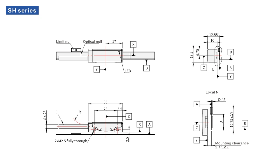
Installation determines how effectively the encoder’s specified performance can be transferred to the machine. Scale straightness, readhead alignment, mounting-surface stability, and travel direction must remain within the required conditions.
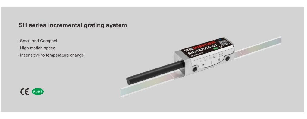
The measurement line should be placed close to the point that determines process quality. If the scale measures movement along one line while the tool or workpiece is offset from it, angular movement in the structure can create additional displacement at the process point.
Temperature can produce an even larger effect. The approximate dimensional change of a machine component can be calculated as:
Length change = thermal expansion coefficient × original length × temperature change
For a one-metre structure with a thermal expansion coefficient of 10 μm/(m·°C), a 1°C temperature increase produces:
Length change = 10 μm/(m·°C) × 1 m × 1°C = 10 μm
This 10 μm dimensional change is larger than the SH04 MC Type positioning accuracy of ±2.5 μm/m. The comparison shows that thermal movement in the machine structure may become the dominant error source even when the feedback device meets its specification.
Stable precision therefore requires suitable materials, controlled warm-up, consistent ambient conditions, appropriate mounting, and compensation where necessary. The stated 0–65°C operating range confirms where the encoder can function; it does not replace thermal control of the complete equipment.
How to Choose a High Precision Linear Encoder
1.Define the Required Accuracy Level
The selection of a high precision linear encoder should begin with the positioning accuracy required by the machine. Instead of focusing only on encoder resolution, consider the final accuracy requirement of the tool, inspection system, or motion platform.
2.Match Encoder Performance with Motion Requirements
Different applications require different balances between precision and speed. High-speed motion systems usually need fast signal response, while inspection and alignment equipment may prioritize finer measurement feedback.
3.Confirm Controller and System Compatibility
The encoder should be compatible with the existing motion control system, including signal format, input requirements, and installation conditions. Proper integration helps ensure stable operation after installation.
4.Consider Installation and Operating Conditions
Mechanical space, measuring length, cable arrangement, temperature variation, and environmental conditions should be evaluated before selecting an encoder model to avoid performance limitations during operation.
5.Evaluate Accuracy at the Machine Level
Encoder accuracy is only one part of the complete positioning system. Mechanical structure, alignment, thermal stability, and calibration can also affect the final positioning performance.
Conclusion
Resolution determines the smallest output increment, accuracy describes how closely the reported position matches the actual position, and repeatability shows how consistently the machine returns to the same point.
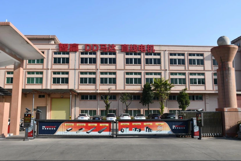
Smartwin SH04 MC Type provides 1.0 μm, 0.5 μm, and 0.1 μm resolution options with maximum response speeds of 3.2 m/s, 2.4 m/s, and 0.9 m/s. It also offers ±2.5 μm/m positioning accuracy, a 40 μm grating pitch, ABZ differential output, and operation from 0–65°C.
The correct configuration depends on the required balance of positioning detail, speed, controller capability, installation accuracy, and thermal stability.
Frequently Asked Questions
1.Does 0.1 μm resolution mean 0.1 μm accuracy?
No. Resolution and accuracy describe different performance characteristics of a linear encoder. A 0.1 μm resolution means the encoder can detect and output position changes in 0.1 μm increments, while accuracy refers to the deviation between the measured position and the actual position. The final positioning accuracy also depends on machine structure, installation conditions, temperature changes, and calibration.
2.Which SH04 MC configuration provides the highest speed?
The 1.0 μm configuration is designed for applications that require faster motion response. It supports a higher response speed compared with finer resolution options, making it suitable for high-speed automation equipment where maintaining stable feedback during rapid movement is important.
3.When is the 0.1 μm version suitable?
The 0.1 μm configuration is suitable for applications that require finer position feedback and precise motion adjustment. It is commonly considered for inspection systems, alignment equipment, and precision platforms where small positioning changes need to be detected accurately.
4.What does ±2.5 μm/m accuracy mean?
The ±2.5 μm/m specification indicates the possible measurement deviation over a one-metre measuring length under specified conditions. It helps users evaluate whether the encoder performance matches the accuracy requirements of their motion system, but it should be considered together with mechanical and environmental factors.
5.What controller interface is required for SH04 MC Type?
SH04 MC Type uses ABZ differential output, which is commonly used in industrial motion control systems. Before installation, users should confirm that the controller, servo drive, or motion card supports this signal type and can handle the required input frequency for stable operation.
6.Which applications are suitable for SH04 MC Type?
SH04 MC Type is suitable for precision motion systems that require reliable position feedback, including high-speed automation equipment, display manufacturing equipment, lithium battery production lines, SMT machines, and other industrial platforms where accurate linear positioning is required.
Back To List