

 En



Can You Replace a Magnetic Linear Encoder Without Changing the Scale or Controller?
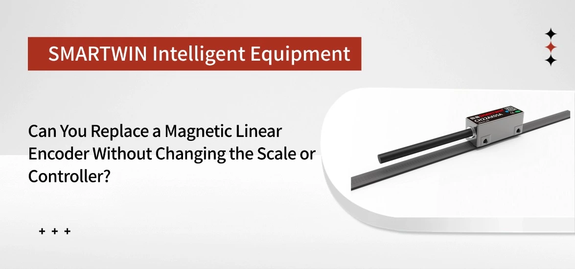
A magnetic linear encoder can sometimes be replaced without changing the original magnetic scale or motion controller. If the replacement readhead supports the existing scale and feedback interface, the rest of the measurement system may remain in place. However, matching resolution or connector type alone is not enough to ensure compatibility.
The decision depends on several technical details, including magnetic pole pitch, scale encoding, signal output, and mounting requirements. Understanding these differences can help equipment engineers avoid unnecessary modifications and identify a suitable replacement for an existing motion system.
When Can You Replace Only the Magnetic Encoder Readhead?
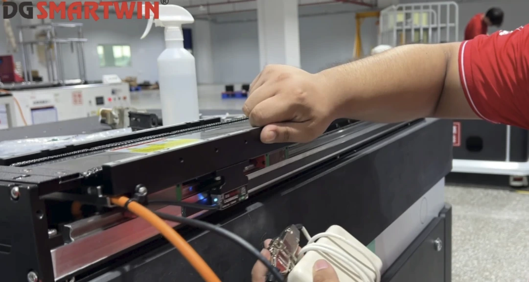
A readhead-only replacement is often considered when the original encoder fails or becomes unavailable. Keeping the existing magnetic scale and controller can reduce installation work, particularly on long-travel machines where removing the scale would involve significant mechanical changes. Whether this approach works depends on the condition and configuration of the original system.
| Existing System Condition | Replacement Approach |
| Scale, electrical interface, and mounting are compatible | Replace the readhead and verify operation |
| Scale is compatible, but installation or controller settings differ | Adjust the mounting or configuration |
| Scale encoding or controller interface is incompatible | Select another encoder or replace the affected components |
| Magnetic scale is damaged | Replace the scale and verify the measurement system |
Before selecting a replacement, it is worth confirming that the readhead is actually responsible for the fault. Damaged cables, loose connectors, or incorrect alignment can also cause unstable position feedback. Identifying the source of the problem first may prevent unnecessary component replacement.
How to Check Magnetic Scale Compatibility Before Replacement
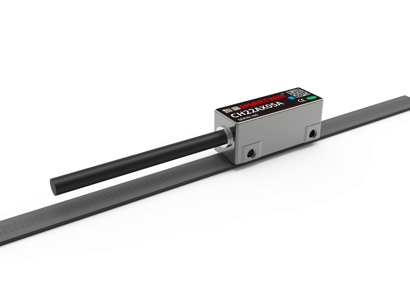
Magnetic scale compatibility is the first technical issue to resolve when retaining the original scale. The readhead must recognize the scale's magnetic pattern and convert it into valid position information. Even products with identical resolution can use different magnetic arrangements, making their readheads incompatible.
1. Check Magnetic Pole Pitch and Scale Type
Magnetic pole pitch describes the spacing of magnetized poles along the scale. Readheads are designed for particular magnetic patterns, so a mismatch may cause inaccurate readings or prevent the sensor from detecting movement correctly.
The original scale model is the most useful starting point. Its documentation should identify the pole pitch, magnetic track arrangement, measuring length, and supported readhead types. These details are more relevant to replacement compatibility than resolution alone.
For example, two encoders with 1.0 μm resolution may use entirely different magnetic patterns. Although they provide the same measurement increment, their readheads are not necessarily interchangeable. Where the existing scale cannot be identified, technical evaluation or sample testing may be needed.
2. Check Incremental Reference Marks and Absolute Coding
Incremental and absolute magnetic encoders place different demands on the existing scale. An incremental system measures changes in position as the axis moves, while its reference mark, when present, allows the controller to establish a known position during homing. A replacement that cannot detect the original reference arrangement may interfere with this procedure.
An absolute magnetic encoder uses an encoded pattern to identify position. Even if another readhead supports the same pole pitch, it may not recognize that pattern. This is especially relevant when replacing discontinued absolute encoders, where the original magnetic scale may use a manufacturer-specific coding arrangement.
How to Verify Encoder Controller Compatibility
Once a suitable readhead-and-scale combination has been identified, attention turns to the existing controller. The replacement must provide an electrical signal and position-data format that the controller can interpret correctly. Otherwise, the encoder may produce feedback without delivering usable position information to the machine.
1. Match Encoder Output Signals and Electrical Requirements
Incremental encoders commonly use ABZ signals, with A and B providing movement information and Z serving as a reference signal. For an existing ABZ system, the replacement's supply voltage, output circuit, signal levels, and connector pinout need to match the controller requirements.
Absolute systems use communication protocols such as BiSS-C or Tamagawa, depending on the encoder configuration. A controller supporting one protocol cannot automatically be assumed to support the other, even when both encoders provide absolute position feedback.
| Output Interface | Main Compatibility Checks |
| ABZ Differential | Voltage, signal levels, channel configuration, wiring |
| BiSS-C | Protocol support, position-data format, communication timing |
| Tamagawa | Protocol configuration, controller support, wiring |
Connector appearance is not a reliable indication of compatibility. Similar connectors may use different pin assignments, making a comparison of the original and replacement wiring diagrams necessary before installation.
2. Verify Encoder Resolution and Controller Settings
A replacement encoder can communicate correctly while reporting the wrong displacement if its output resolution differs from the controller's configuration.
For example, suppose a controller is configured for 1,000 counts/mm, but the replacement produces 2,000 counts/mm under the same counting method. Without updating the scaling parameter, a physical movement of 10 mm would be interpreted as 20 mm.
At higher travel speeds, the controller must also process the incoming signals without missing counts. For absolute interfaces, position-data format and communication settings require similar attention. These checks help establish whether the replacement can operate with the original control configuration or needs parameter adjustments.
Check Magnetic Encoder Readhead Mounting and Installation Gap
Even when the electrical interface is compatible, the replacement readhead must fit the existing motion assembly. Mounting-hole positions, housing dimensions, cable routing, and available clearance all affect whether the original installation can be retained. Minor dimensional differences may be accommodated with a suitable bracket, provided it maintains sufficient rigidity and alignment.
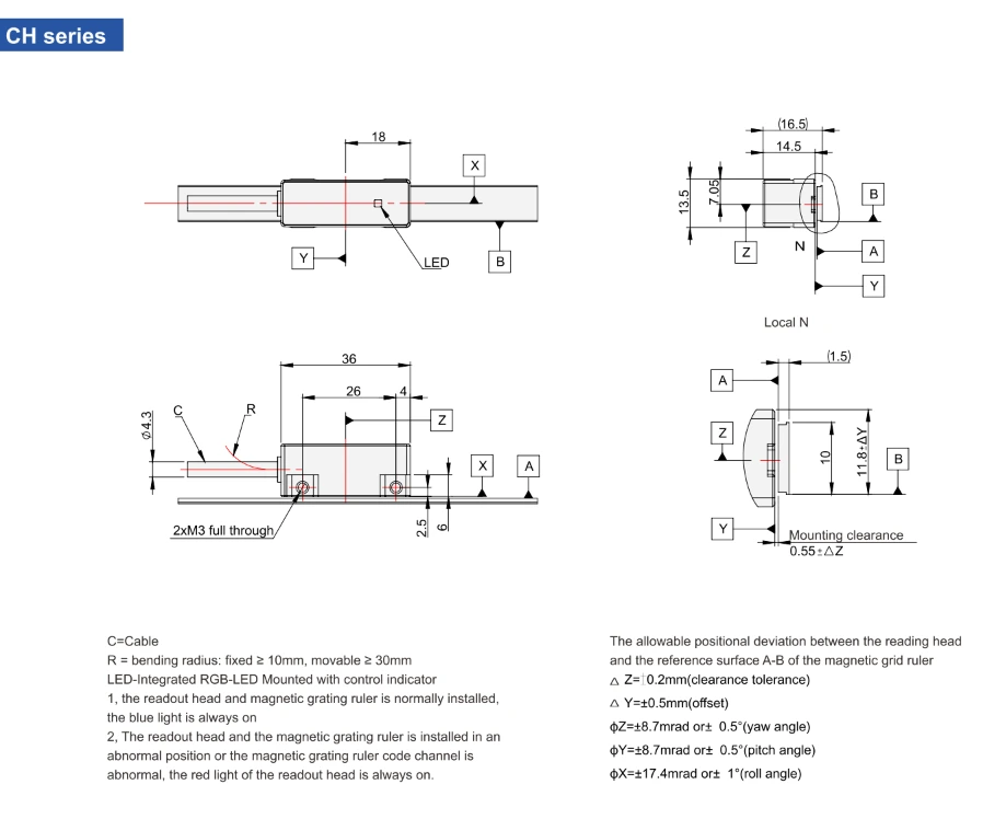
The installation gap between the readhead and magnetic scale must remain within the manufacturer's specified range. Excessive distance, lateral offset, or incorrect orientation can affect signal detection. This is particularly important on long-travel equipment, where slight variations in the mounting surface may change the sensing gap along the axis.
Rather than checking alignment at only one position, the readhead should be inspected across the usable travel range. The replacement model's installation drawing provides the appropriate reference for mounting dimensions and tolerances.
How to Test a Replacement Magnetic Linear Encoder
A replacement should be evaluated under the machine's actual operating conditions before normal production resumes. Initial communication confirms that the controller can receive feedback, but it does not establish that the reported position remains correct throughout the full travel range.
After recording the original controller parameters and completing installation and electrical safety checks, begin with controlled movement at low speed. Compare the reported displacement with a known physical distance and confirm that position changes in the correct direction. Incremental systems should complete their reference or homing procedure, while absolute systems should be checked for the expected position recovery after a controlled power cycle.
Testing should then extend to the complete measuring length and intended operating speed.
| Test Item | Expected Result |
| Known-distance movement | Reported displacement matches actual travel |
| Position direction | Feedback follows physical movement correctly |
| Reference or homing | Reference position is established as expected |
| Full-stroke movement | Stable feedback without unexpected signal loss |
| Operating-speed test | No missed counts or communication errors |
| Repeated positioning | Consistent position feedback |
If errors appear only at certain positions or speeds, the cause may involve mechanical alignment, signal frequency, or controller configuration. The machine should return to production only after the replacement meets its required positioning and safety conditions.
CH22 and CA26 Magnetic Encoder Replacement Considerations
The existing feedback architecture helps narrow down suitable replacement options. Incremental and absolute systems require different signal interfaces and position-recovery arrangements, so the original encoder type is an important starting point.
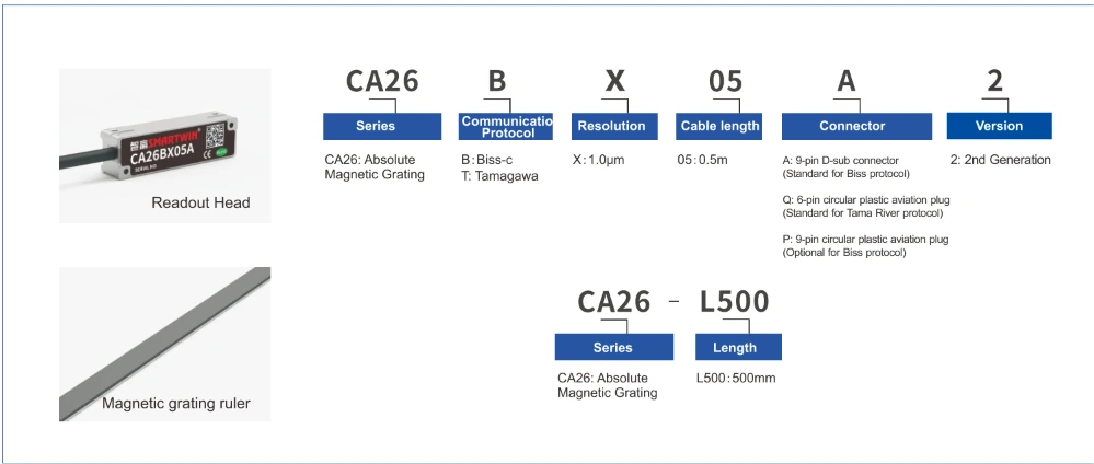
Smartwin's CH22 and CA26 provide two examples of these configurations. Their suitability for a particular replacement depends on the original scale and controller rather than matching product specifications alone.
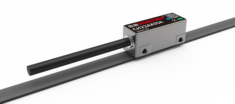
1. CH22 Incremental Magnetic Encoder for ABZ Systems
For equipment using incremental ABZ feedback, retaining the original controller may be possible when the replacement provides the required electrical output.
The CH22 is an incremental magnetic encoder with 1.0 μm resolution, ABZ differential output, and a maximum response speed of 5 m/s. Its effective measuring length reaches 50 m, which is relevant when evaluating replacement options for long-travel automation equipment.
When considering CH22, the key questions are whether the controller accepts its ABZ configuration and whether the existing magnetic scale supports the required sensing arrangement. Matching the interface does not, by itself, establish readhead-and-scale compatibility.
2. CA26 Absolute Magnetic Encoder for Position Feedback
Absolute feedback systems require a different assessment because the readhead must interpret the magnetic scale's position coding and transmit that information through a supported controller interface.
The CA26 provides 1.0 μm resolution, BiSS-C and Tamagawa protocol options, and a maximum response speed of 5 m/s. Its effective measuring length reaches 16 m.
For equipment requiring absolute position feedback after a power interruption, these specifications may help determine whether CA26 is appropriate for the existing motion system. However, retaining the original magnetic scale is only possible if its coding arrangement is compatible with the selected readhead.
Magnetic Linear Encoder Replacement FAQs
1. Can I replace a magnetic encoder readhead with another manufacturer's model?
Cross-manufacturer replacement is possible in some systems, but similar specifications do not guarantee compatibility. The replacement must support the original scale's magnetic arrangement and the controller's electrical interface. Compatibility should be confirmed through technical documentation or testing.
2. Does matching magnetic pole pitch guarantee compatibility?
No. Pole pitch is only one part of the scale design. Magnetic tracks, reference marks, and absolute coding may differ between systems, so the complete readhead-and-scale combination must be evaluated.
3. Can an incremental magnetic encoder be replaced with an absolute encoder?
Yes, as part of a system upgrade, but usually not through a simple readhead swap. The magnetic scale and controller interface may need to change, along with the relevant control settings.
4. Why are position readings incorrect after an encoder replacement?
Incorrect controller scaling, signal wiring, reference configuration, or readhead alignment can cause position errors. Absolute systems may also be affected by incompatible position-data settings. Comparing feedback against a known physical displacement can help isolate the problem.
Conclusion
Replacing a magnetic linear encoder without changing the scale or controller can reduce maintenance work, but only when the new readhead matches the existing measurement system. The most reliable approach is to establish scale compatibility first, confirm the controller interface, and verify positioning performance after installation.
For incremental or absolute feedback applications, CH22 and CA26 offer different configurations to consider. If you are evaluating an existing system, share the encoder model, magnetic scale details, and controller specifications with Smartwin to discuss a suitable replacement approach.
Back To List