

 En



When Should You Use an Ironless Linear Motor for Precision Scanning?
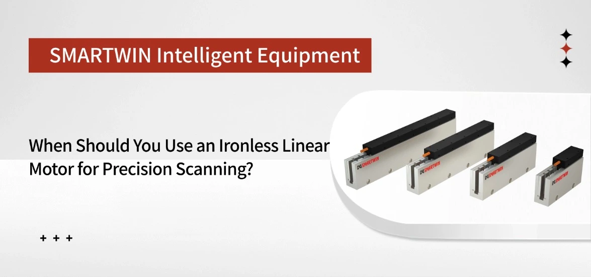
An ironless linear motor is worth considering when precision scanning requires steady low-speed movement, minimal cogging-related disturbance, or frequent acceleration between measurement positions. These characteristics are particularly useful in optical inspection, metrology, and lightweight scanning stages. However, the best motor choice depends on which aspect of motion limits the inspection process, as well as the force, thermal, and positioning requirements of the complete system.
When Does Precision Scanning Benefit from an Ironless Linear Motor?
Scanning equipment operates in different ways. Some systems acquire measurements while moving continuously, while others stop at individual positions before collecting data. Each method places different demands on the motor.
1. Continuous Scanning at Low or Constant Speeds
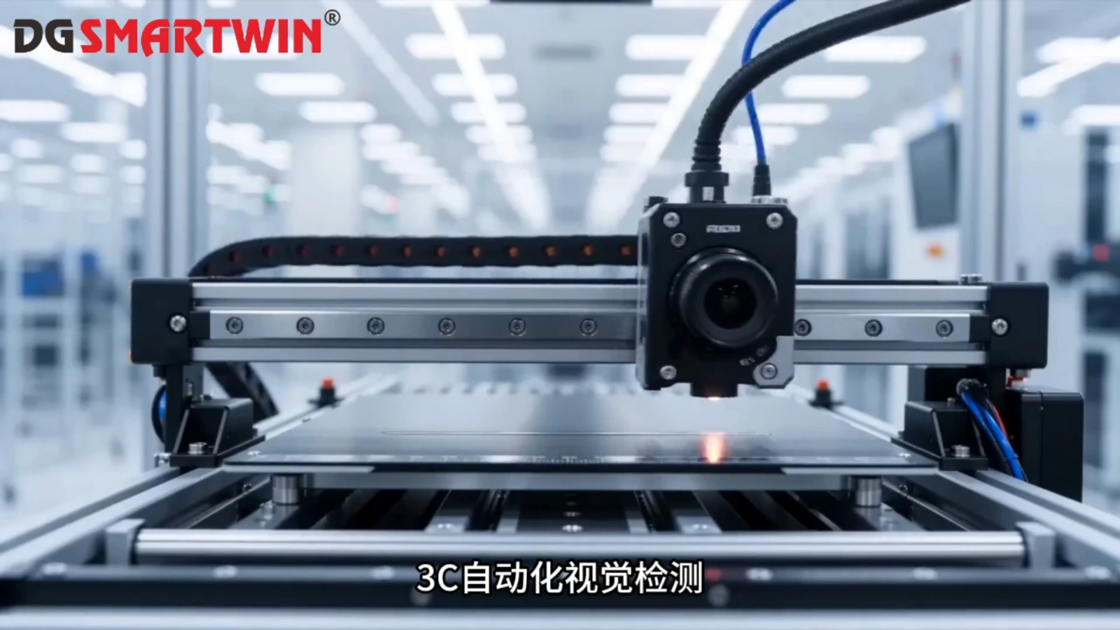
During continuous scanning, the inspection head or workpiece travels along a defined path while a camera or sensor collects data. Maintaining consistent movement is particularly important in line-scan imaging, surface inspection, and optical measurement systems.
When images are captured at fixed time intervals, changes in travel speed can alter the spacing between measurements. This may introduce geometric distortion or inconsistent sampling along the scan direction. A motor with minimal cogging-related disturbance can make stable velocity control easier, especially at low speeds where periodic force variations may become more noticeable.
The advantage is less significant when the scanning system already maintains acceptable velocity tracking or compensates effectively for position variations.
2. Repeated Positioning with Short Settling Times
In step-and-settle inspection, the stage moves to a measurement point, stops, and waits until residual movement falls within an acceptable tolerance. Repeating this process hundreds or thousands of times makes positioning and settling time important to equipment throughput.
A lightweight ironless moving coil can support responsive acceleration and deceleration, while the absence of cogging avoids one source of position-dependent disturbance. These characteristics make ironless motors worth evaluating for inspection stages with frequent short moves.
The actual cycle-time improvement must be established through complete-stage testing rather than inferred from the motor structure alone.
3. Lightweight Scanning Stages with Frequent Motion Changes
Compact inspection platforms often carry relatively light cameras, optical sensors, or measurement tools. When these stages repeatedly accelerate or reverse direction, moving mass becomes an important factor in motor sizing.
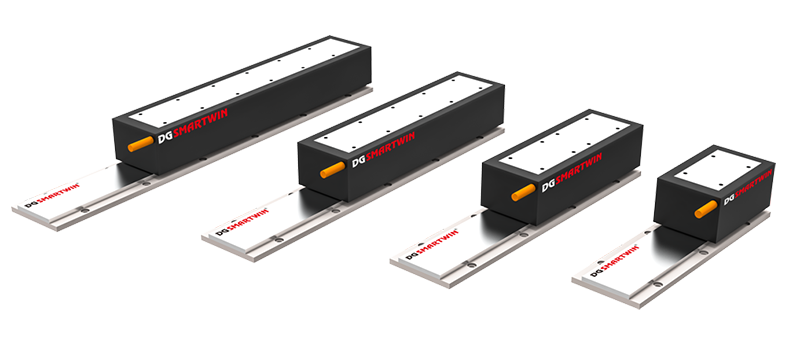
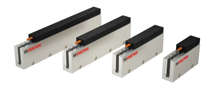
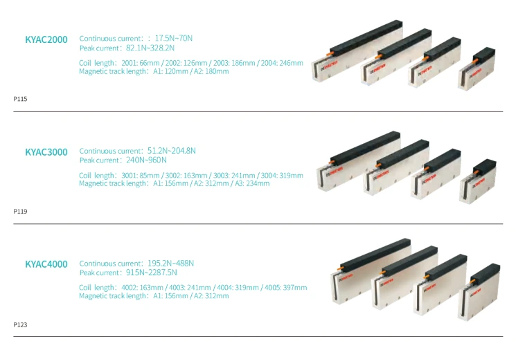
For example, SMARTWIN's CUM2B ironless linear motor provides 25.5 N of continuous thrust and 127.6 N of peak thrust. The difference illustrates why a lightweight scanning axis must be evaluated for both sustained operating force and short acceleration demands. Whether this configuration is suitable depends on the total moving mass, motion profile, and thermal conditions.
For applications with frequent direction changes, calculating the required force over the complete cycle is more useful than selecting a motor based on peak thrust alone.
How Do Cogging Force and Velocity Ripple Affect Scan Quality?
A scanning stage must follow its commanded motion closely enough to preserve the relationship between physical position and measurement data. One source of unwanted movement is the periodic force generated by the motor itself.
1. Why Cogging-Free Motion Matters at Low Speeds
In an iron-core linear motor, interactions between the iron teeth and permanent magnets produce position-dependent cogging forces. These forces can disturb motion as the motor travels along the magnetic track.
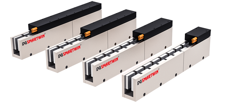
An ironless winding contains no ferromagnetic teeth, removing this source of cogging and the corresponding attraction between the moving coil and magnet assembly. The result is a smoother electromagnetic force characteristic that is valuable when a scanning axis must maintain consistent movement over small distances.
However, cogging force and force ripple are not identical. Variations in motor current, commutation, and magnetic field distribution can still produce thrust disturbances in an ironless design.
2. How Velocity Ripple Influences Measurement Results
Thrust disturbances can create acceleration and velocity fluctuations that affect the spacing or position of acquired data. Their impact depends on how the measurement system synchronizes sampling with stage movement.
In line-scan imaging, for example, fixed-time acquisition can produce uneven image-line spacing when velocity varies. Position-triggered acquisition reduces sensitivity to this particular error, although vibration during exposure may still affect image quality.
The relevant performance measure is therefore not simply whether the motor is cogging-free, but whether the completed scanning axis can maintain the required velocity tracking and position stability under its operating conditions.
Can an Ironless Linear Motor Improve Scanning Accuracy and Settling Time?
Smooth travel can support measurement consistency, but it should not be confused with absolute positioning accuracy. Similarly, a responsive motor does not automatically guarantee that an inspection stage will settle quickly.
1. Motion Smoothness Versus Positioning Accuracy
A stage may move at a consistent velocity yet still deviate from its intended position because of encoder errors, guide misalignment, thermal expansion, or structural deformation.
For this reason, engineers should distinguish velocity stability from position accuracy when evaluating precision scanning equipment. An ironless motor reduces a specific electromagnetic disturbance, while the encoder, mechanical assembly, and controller determine how accurately the complete axis follows its commanded path.
Performance should be verified using measured position or tracking errors at the intended scanning speed rather than relying on a general high-precision motor designation.
2. What Determines Settling Time After Movement?
Settling time is the period required for a stage to remain within its specified position or vibration tolerance after completing a move. The acceptable tolerance depends on the measurement task.
A lower moving mass can reduce the force needed for acceleration, but mechanical resonance, structural rigidity, and servo tuning determine how residual oscillation decays. A fast motor installed on a flexible stage may still require substantial time before measurement can begin.
For repeated-positioning inspection equipment, comparing settling performance under the same travel distance, payload, motion profile, and tolerance provides a more useful result than comparing motor acceleration specifications alone.
When Might an Iron-Core Linear Motor Be a Better Choice?
An ironless design is not always necessary, particularly when a scanning system needs greater continuous force or has less demanding smoothness requirements.

Iron-core motors generally provide higher force density for a comparable size, making them attractive for heavier stages and applications where sustained thrust is the primary concern. Proper motor design and control compensation can also reduce the impact of cogging, although the resulting motion performance must still meet the equipment's requirements.
| Scanning Requirement | Selection Consideration |
| Stable movement during low-speed scanning | Prioritize evaluating ironless designs |
| Frequent positioning with short settling requirements | Compare complete-stage settling performance |
| High payload or continuous thrust demand | Compare motor force density and thermal capacity |
| Moderate smoothness requirements and cost constraints | An iron-core solution may be sufficient |
| Extended continuous scanning | Verify RMS force and heat dissipation |
Thermal performance deserves particular attention during continuous operation. A motor may handle acceleration peaks successfully but exceed its continuous thermal capacity when the movement is repeated throughout a production shift.
If the main limitation is payload capacity rather than motion disturbance, a suitably designed iron-core system may provide a more practical balance of performance, size, and cost.
What Should Engineers Verify Before Choosing a Motor for Precision Scanning?
The starting point is a defined motion profile: travel distance, scanning speed, moving mass, acceleration, and allowable tracking error. For equipment that stops between measurements, the required settling tolerance and cycle time must also be established.
These conditions determine the peak force needed during acceleration and the RMS force associated with repeated operation. Continuous thrust, operating temperature, and available cooling then help establish whether the motor can sustain the expected duty cycle.
System integration is equally important. Encoder feedback, servo-drive compatibility, mechanical alignment, and stage rigidity should be reviewed before final selection. If an existing scanning axis produces inconsistent results, measuring velocity error, position deviation, or residual vibration can help identify whether the problem originates in the drive system or elsewhere in the mechanism.
Frequently Asked Questions
1. Is an Ironless Linear Motor Necessary for Every Precision Scanning System?
No. It is particularly useful when low-speed movement, cogging-related disturbances, or lightweight dynamic motion are important. If an inspection axis already meets its scanning requirements, switching to an ironless design may offer little practical benefit.
2. Can an Ironless Linear Motor Eliminate All Velocity Ripple?
No. Although it eliminates cogging caused by iron teeth, variations in motor current, control behavior, friction, and mechanical vibration can still affect velocity. The complete motion system must be evaluated to confirm scanning stability.
3. What Specifications Matter Most When Selecting a Motor for an Inspection Stage?
Key requirements include moving mass, stroke, scanning speed, acceleration, continuous and peak force, operating cycle, and acceptable motion error. Encoder compatibility, installation space, and thermal conditions are also necessary for confirming a suitable configuration.
Conclusion
An ironless linear motor is most valuable when its cogging-free operation and lightweight moving structure address a specific scanning requirement, such as low-speed velocity stability or frequent positioning. For heavier loads or less demanding motion conditions, an iron-core alternative may be equally suitable.
The final choice should be based on measured motion requirements and the complete stage design. SMARTWIN can assist with evaluating these conditions and selecting an appropriate motor configuration for precision inspection equipment.
Back To List