

 En



Why Is Your Magnetic Linear Encoder Giving Unstable Position Feedback?

A magnetic linear encoder may produce unstable position feedback when the readhead shifts out of alignment, metal particles interfere with the magnetic scale, or electrical noise disrupts the signals reaching the controller. Depending on the fault, the machine may show sudden position jumps, missing counts, or intermittent feedback loss.
A faulty reading does not necessarily mean the encoder needs replacement. Before changing components, examine how the error develops. Does it occur at the same location, only during fast movement, or when nearby electrical equipment starts? Those differences often reveal more about the problem than the error message itself.
What Does Unstable Magnetic Linear Encoder Feedback Look Like?
An unstable reading can appear long before the controller reports a complete feedback failure. A positioning stage may overshoot its expected location, return inconsistent coordinates after repeated moves, or display a small position change while the axis is stationary.
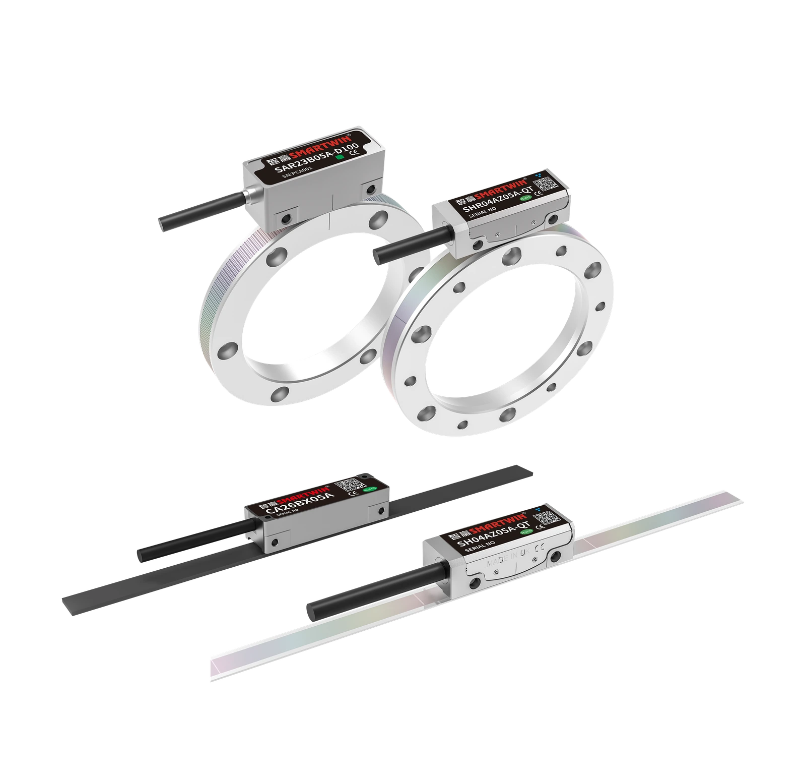
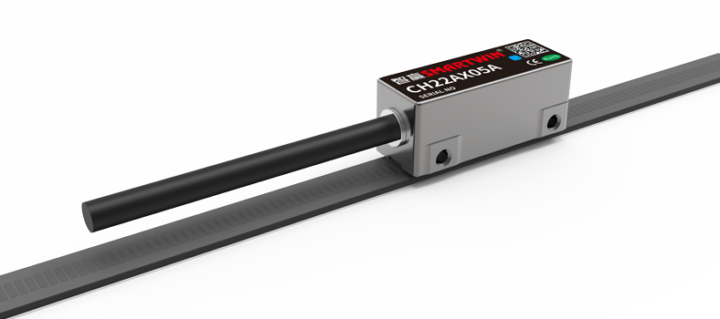
The first task is to establish whether the reported movement matches what the machine actually does. For an incremental system such as Smartwin's CH22, a missed or incorrectly counted signal transition can change the controller's calculated position without any corresponding change in physical travel.
The following table connects common symptoms with useful initial checks.
| Fault Symptom | Possible Cause | First Check |
| Sudden position jump | Noise or incorrect pulse counting | Feedback signal and controller input |
| Error repeats at one position | Local scale damage or contamination | Affected scale section |
| Feedback becomes unstable at high speed | Signal integrity or input-frequency limitation | Encoder and controller specifications |
| Position fluctuates at standstill | Electrical noise or actual axis vibration | Physical motion and feedback trace |
| Intermittent signal loss | Loose connection or unstable supply | Power and connectors |
| Error varies along the stroke | Changing readhead gap or alignment | Mounting geometry across travel |
These observations should be recorded before making adjustments. If the error occurs only on certain movements, note the position, speed, direction, and operating state of the servo drive. A repeatable pattern makes it much easier to distinguish a sensing problem from an issue elsewhere in the motion system.
What Causes Magnetic Linear Encoder Signal Instability?
The readhead of a linear magnetic encoder follows the encoded magnetic pattern on a measuring scale. This requires a consistent sensing gap, an intact magnetic pattern, and a reliable electrical connection to the controller. Problems in any of these areas can affect position measurement, although the symptoms are not always the same.
1. Incorrect Air Gap and Readhead Alignment
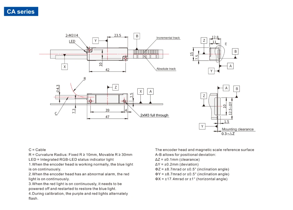
The magnetic encoder air gap must remain within the range specified for the particular readhead and scale. Excessive clearance, lateral offset, or incorrect orientation can reduce the reliability of magnetic signal detection.
A mounting problem may be difficult to identify when the machine is stationary. For example, a bracket that flexes during acceleration can change the sensing gap even if the initial alignment was correct. On a long-travel axis, differences in the mounting surface may also become noticeable only near the ends of the stroke.
Smartwin's CH22 supports an effective detection length of up to 50 m. This specification makes the model relevant to extended linear motion systems, but it also illustrates why checking alignment at the home position alone is insufficient. The installation must maintain the required readhead-to-scale relationship throughout the actual working stroke.
2. Magnetic Contamination and Scale Damage
Ordinary dust or oil does not affect magnetic sensing in the same way it can obstruct an optical measuring system. Ferromagnetic particles, however, can interfere with the magnetic field near the scale. Fine steel debris is particularly worth checking around machinery that handles or processes metal components.
The location of the fault provides an important clue. If the encoder consistently reports an error as the readhead crosses one section of the scale, inspect that area for trapped particles, physical deformation, or damage to the magnetic pattern.
Cleaning may resolve a contamination problem, but it cannot necessarily restore a damaged magnetic scale. Avoid abrasive tools or strong magnets during inspection, and follow the cleaning instructions for the installed encoder.
3. Electrical Noise, Wiring and Power Issues
The signal can be affected even when the readhead and magnetic scale are correctly installed. Motor power cables, servo drives, contactors, and switching devices may introduce electrical noise into nearby feedback wiring. Damaged shielding, poor connections, or unsuitable grounding can make the system more susceptible to interference.
This is particularly relevant when position errors coincide with acceleration or electrical switching. IEC 61800-3:2022 establishes electromagnetic compatibility requirements for adjustable-speed power drive systems and machine tools, highlighting the importance of managing electrical emissions and immunity in industrial motion systems. The standard provides an EMC framework rather than model-specific encoder wiring instructions.
Supply voltage and receiving-interface settings should also be checked. A linear encoder may detect motion correctly, yet the controller may fail to interpret the feedback if the signal levels, wiring, or input configuration are unsuitable.
How Do You Troubleshoot a Magnetic Linear Encoder Step by Step?
Effective magnetic linear encoder troubleshooting starts with the evidence already available from the machine. Before replacing the readhead or magnetic scale, establish a baseline using the controller's position trace, fault history, and the operating conditions under which the problem occurs.
1. Inspect the Scale and Readhead Installation
After safely stopping the machine and isolating hazardous energy, examine the scale and readhead mounting. Look for loose fasteners, damaged scale sections, accumulated metal particles, and brackets that may shift under mechanical load.
Measure the gap and alignment against the manufacturer's installation requirements. If the fault occurs near a particular location, inspect the mounting geometry around that area and compare it with a section where feedback remains stable.
Where equipment permits, use an appropriate mechanical measurement method to check alignment at several points along the axis. This is more informative than repeatedly adjusting the readhead until the controller temporarily stops reporting an error.
2. Check Wiring, Power and Feedback Signals
Examine the encoder cable from the readhead to the receiving controller. Check connectors for looseness, inspect areas exposed to repeated bending, and verify the encoder supply voltage under the relevant operating conditions.
For Smartwin CH22, the ABZ differential interface carries incremental position information. The A and B channels provide quadrature signals used to determine movement and direction, while the Z channel supplies a reference marker. If the controller's calculated position changes unexpectedly, inspect signal reception and confirm that the input configuration matches the encoder.
Rockwell Automation's motion-control documentation describes feedback noise faults associated with abnormal A/B channel transitions, including interference picked up by encoder wiring. Examining these signals with suitable measurement equipment can help distinguish a wiring or reception problem from an issue with mechanical movement.
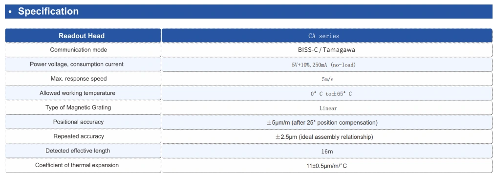
For an absolute magnetic linear encoder such as Smartwin CA26, the diagnostic approach changes. The CA26 supports BiSS-C communication and includes an LED status indicator. Its controller interface should therefore be checked for valid position frames, communication errors, and correct configuration.
The official BiSS-C protocol includes cyclic redundancy checks (CRC) for detecting transmission errors. Where the controller exposes CRC or related diagnostic information, those records can help determine whether unreliable feedback is associated with communication rather than the magnetic sensing mechanism. The LED states should be interpreted using the CA26's own technical documentation.
3. Repeat the Fault Under Controlled Operating Conditions
Once the installation and electrical checks are complete, test the axis using an approved motion procedure. Begin with low-speed travel and record the reported position, actual movement where it can be independently measured, and any feedback alarms.
Then repeat the affected motion at the operating speed and direction that previously produced the error. If the problem occurs only during acceleration, investigate dynamic cable movement, vibration, and electrical switching. If it appears at the same scale location regardless of direction or speed, return to the local sensing and mounting conditions.
Change one suspected cause at a time where practical. When several adjustments are made together, it becomes difficult to determine which action resolved the problem or whether the error may return.
Why Does the Encoder Fail Only at Certain Speeds or Positions?
Faults associated with a particular travel location and faults associated with increasing speed should not be diagnosed in the same way.
A position-dependent error may indicate magnetic scale contamination, local damage, or a change in sensing gap. Testing the same section in both directions helps determine whether the problem follows the scale or occurs under a particular mechanical load.
Speed-dependent problems are often more difficult to isolate. In an incremental feedback system, faster movement increases the rate of signal transitions the controller must receive and count. Electrical interference, excessive signal distortion, or inadequate input capability may become apparent only when the machine approaches its normal production speed.
Smartwin's CH22 and CA26 both specify maximum response speeds of 5 m/s. If a system develops feedback errors while operating below that limit, the rated speed alone does not establish the cause. For CH22, the investigation should include quadrature signal quality and controller counting capability. For CA26, communication validity and the configured BiSS-C interface are more relevant.
The distinction matters because reducing the axis speed may temporarily eliminate an error without resolving the underlying problem. The fault should be reproduced and investigated under the conditions in which the equipment is expected to operate.
How Can You Verify That Position Feedback Is Stable Again?
A feedback problem is not resolved simply because the controller no longer displays an alarm. The original operating conditions must be repeated to confirm that the fault has actually disappeared.
Run the axis through the affected section in both directions, then test the full measuring stroke at normal operating speed. Review the position trace for unexpected jumps, lost counts, or communication errors. If an independent measurement reference is available, compare its results with the encoder feedback at the same physical positions.
For intermittent faults, one successful movement is insufficient. A representative operating cycle should include repeated starts, stops, and changes in speed, particularly if the original issue occurred during continuous production.
It is also important to distinguish stable encoder feedback from overall machine accuracy. A high precision linear encoder can report movement consistently while mechanical deflection, thermal expansion, or servo tuning still causes the load to miss its target. When the feedback signal is confirmed stable but positioning errors remain, the investigation should move beyond the encoder.
When Should You Repair or Replace a Magnetic Linear Encoder?
Replacement is worth considering when the magnetic scale has confirmed damage, the readhead fails an applicable diagnostic test, or the system continues to produce invalid feedback after installation and electrical problems have been ruled out.
A damaged cable or connector may require only a localized repair. Similarly, a recurring fault caused by an incorrect sensing gap is normally an installation issue rather than evidence that the encoder has reached the end of its service life.
Before contacting technical support, collect the encoder model, fault position, operating speed, controller interface, and available diagnostic records. For CH22 systems, an A/B signal trace or count-error record may be useful. For CA26 systems, BiSS-C communication diagnostics and the documented readhead status can provide additional evidence.
Smartwin develops magnetic encoders alongside linear motors, motion modules, drives, and other motion-control components. This allows feedback problems to be reviewed in the context of the complete motion system, particularly when the cause is difficult to isolate between the encoder, controller, and mechanical installation.
Magnetic Linear Encoder Troubleshooting FAQs
1. Why does my magnetic encoder position reading jump when the axis is stationary?
A sudden position change at standstill can result from electrical interference, incorrect feedback interpretation, or actual movement caused by vibration or servo oscillation. Compare the controller's position trace with the physical axis before assuming the encoder is defective. For incremental systems, inspecting the received A/B signals may help identify false or missing transitions.
2. Can metal chips cause a magnetic linear encoder to lose position?
Yes. Ferromagnetic particles such as iron or steel debris can affect the magnetic field near the scale and interfere with position detection. The fault may be intermittent or concentrated around a contaminated area. Inspect the scale, clean it using an approved method, and repeat the movement to check whether the feedback has recovered.
3. Can an incorrect readhead gap cause intermittent encoder signal loss?
Yes. If the readhead-to-scale clearance moves outside the specified range, magnetic signal detection may become unreliable. The problem can occur only at certain positions or during acceleration if the mounting structure shifts. Measure the gap at multiple locations along the stroke rather than relying on the initial installation position.
4. Why does an incremental encoder lose position after a power interruption?
An incremental encoder reports changes in position rather than a unique absolute position at every location. If the controller loses its stored count or reference when power is interrupted, the axis may require homing before normal operation resumes. An absolute linear encoder such as the Smartwin CA26 provides absolute position information, but the controller must still receive and interpret that data correctly after startup.
Conclusion
Unstable magnetic linear encoder feedback can originate from the readhead installation, magnetic scale, wiring, or controller interface. The most reliable way to identify the cause is to examine where the error occurs, check the relevant signals, and verify the result under normal operating conditions.

For systems using Smartwin CH22 or CA26 encoders, contact Smartwin with your installation details and fault records to discuss the appropriate troubleshooting approach.
References
1. International Electrotechnical Commission (IEC). IEC 61800-3:2022 — Adjustable Speed Electrical Power Drive Systems: EMC Requirements and Specific Test Methods for PDS and Machine Tools.
2. Rockwell Automation. MotFeedbackNoiseFault — Studio 5000 Logix Designer Online Help.
3. BiSS Interface. BiSS C Protocol Description, Revision D2.
4. Smartwin. CH22 Incremental Magnetic Encoder: Features and Applications.
5. Smartwin. CA26 Absolute Magnetic Linear Encoder.
Back To List