Magnetic vs Optical Linear Encoders: Which One Fits Your Application?
Accurate, real-time position feedback lies at the heart of every modern motion system—from factory-floor gantries and pick-and-place robots to semiconductor steppers and coordinate-measuring machines. Two sensing technologies dominate this landscape: optical linear encoders and magnetic linear encoders. Each excels in a different operating envelope, and choosing the wrong one can saddle you with unexpected downtime, missed accuracy targets, or spiraling costs.
This in-depth guide compares the two head-to-head. Along the way, it explains the magnetic linear encoder working principle, digs into installation nuances, and supplies practical checklists so you can match the technology to your real-world environment.
How Each Encoder Senses Motion
| Feature | Optical Linear Encoder | Magnetic Linear Encoder |
|---|---|---|
| Core physics | Light passes through (transmissive) or reflects from (reflective) micron-scale markings on a glass or metal scale; photodiodes create sine/cosine signals. | Hall-effect, AMR, GMR or TMR sensors detect alternating north–south poles on a magnetized linear magnetic encoder strip or bar. |
| Native pitch | As fine as 4 µm; interpolation pushes resolution into nanometers. | 0.5 – 2 mm pole pitch common; interpolation yields 0.05–1 µm resolution. |
| Typical gap | 50–100 µm (tight) | 0.2 – 2 mm (forgiving) |
| Outputs | 1 Vpp analog, A/B/Z quadrature, SSI, BiSS, EnDat | Same portfolio; electronics in the readhead square and encode the magnetic signals. |
Because the magnetic encoder linear design senses a magnetic field rather than light, it can tolerate debris, oil, or scratches that would block or scatter photons in an optical system.
Resolution, Accuracy & Error Sources
Optical Resolution Ceiling
Optical glass scales with 20 µm index marks routinely hit ±0.5 µm total accuracy over a meter and deliver sub-nanometer resolution after ×65 536 interpolation. Glass has an almost negligible coefficient of thermal expansion (CTE ≈ 0 ppm / °C), ensuring stability in climate-controlled metrology rooms.
Magnetic Accuracy Considerations
A linear magnetic encoder relies on pole pitch accuracy (±1–2 µm / m for premium tape) and interpolation non-linearity (INL). State-of-the-art ASICs drive INL below ±40 nm, so overall ±3–5 µm per meter is possible when the tape is bonded to a matching steel substrate. For woodworking routers, welding robots, or pick-and-place heads, that margin easily beats process requirements.
Key Error Budgets
| Contributor | Optical | Magnetic |
|---|---|---|
| Scale accuracy | ±0.5 µm / m (glass) | ±1–2 µm / m (tape) |
| Interpolation NL | ±20 nm | ±40–60 nm |
| Thermal drift | Negligible (glass) | Matches substrate (steel ≈ 11 ppm / °C) |
| Contamination risk | High | Low |
Environmental Robustness
| Condition | Optical Encoder | Magnetic Encoder |
|---|---|---|
| Dust, wood chips, graphite, coolant | Risk of signal dropout; sealed lips add cost. | Magnetic field penetrates non-ferrous debris; counts remain valid. |
| Ferrous chips | N/A (blocked optically) | Can cling to poles and distort field—use cover foil or wiper. |
| Shock & vibration | Spring-loaded optics displace easily; gap loss. | 50 g+ shocks survive thanks to 1 mm gaps and rigid sensor blocks. |
| Temperature range | −10 °C → +80 °C (LED life, condensation) | −40 °C → +125 °C (Hall/AMR sensors) |
| Magnetic fields (MRI, weld gun) | Not affected | Readhead must use non-ferrous screws and shielding, but still functional. |
When the shop floor bristles with coolant spray, abrasive dust, or repeated hammering shocks, rugged magnetic linear encoder tape offers a “fit-and-forget” alternative that still delivers microns of precision.
Installation & Alignment
Scale or Tape Mounting
Optical: Glass or stainless CIP (chrome-on-steel) scales need ±20 µm flatness along the axis and must be protected from twisting loads.
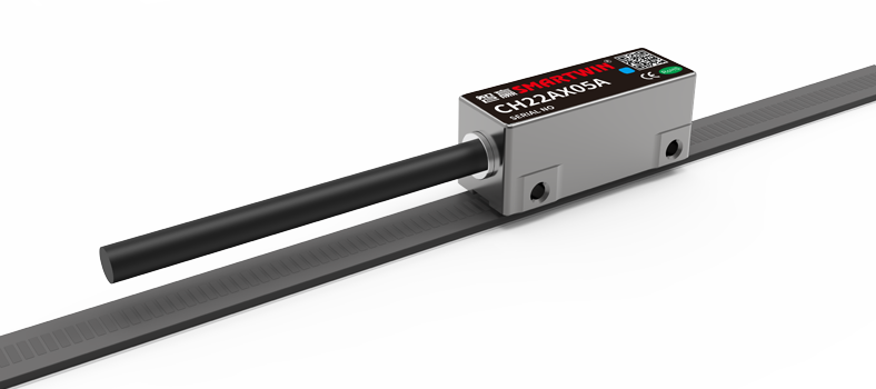
Magnetic: Adhesive-back linear magnetic encoder tape bonds in minutes. Stainless carrier rails add stiffness for long axes. Saw-tooth jigs or scissors cut tape on site.
Readhead Gap & Tilt
Optical: 50–100 µm, shims required, ±1 mrad yaw tolerance.
Magnetic: 0.3–1.0 mm typical, ±5 mrad yaw, pitch, roll. Most manufacturers include LED bars that turn green when amplitude is within 70–130 %.
Calibration Checks
For long-travel machines, laser interferometers map residual scale errors. Optical scales typically need one-time mapping; magnetic systems may benefit from table-based thermal compensation because the tape expands with the machine base.
Cost over Lifetime
| Phase | Optical | Magnetic |
|---|---|---|
| Hardware purchase | High—glass scale machining, precision readhead | 15–40 % lower; simple magnetizing process |
| Install time | Hours; align, purge, seal | Minutes; stick-on tape, wide gap setup |
| Maintenance | Clean optics weekly in dirty shops | Replace wiper yearly; inspect for ferrous dust |
| Crash damage | Glass breaks; downtime + costly replacement | Tape rarely shattered; quick field splice |
When total cost of ownership matters more than sub-micron metrology, magnetic can deliver 3–5 × lower life-cycle expense.
Application-Driven Recommendation
| Use Case | Reason |
|---|---|
| Coordinate-Measuring Machines | Sub-micron volumetric error and zero hysteresis. |
| Semiconductor lithography stages | Nanometer resolution and ultra-low INL. |
| High-precision surface grinders | Mirror finish requires < 0.1 µm feedback jitter. |
| Scientific beamlines | Glass scale’s 0 ppm / °C CTE ensures stability. |
| Use Case | Reason |
|---|---|
| CNC router cutting MDF | Dust & chips cannot block magnetic field. |
| Plasma / waterjet gantry | High heat, splash, metal grit tolerated. |
| Collaborative robot joints | Compact, absolute BiSS-Safety readheads; shock immunity. |
| MRI patient tables | Non-ferrous magnetic encoder linear sensors survive 1.5 T fields. |
| Mobile construction equipment | −40 °C winters, 60 °C hydraulics—magnetic thrives. |
| Question | Optical Advantage | Magnetic Advantage | Your Requirement |
|---|---|---|---|
| Need < 1 µm absolute accuracy? | ✔ | ||
| Operating in oil, dust, or coolant? | ✔ | ||
| Shock > 30 g or gap > 0.5 mm? | ✔ | ||
| Temperature extremes (−30 → +110 °C)? | ✔ | ||
| Budget for premium scales? | ✔ | (Lower cost) ✔ | |
| Need redundancy or SIL-3 safety? | ✔ (BiSS-Safety) |
The column with the most checks reveals the better technology for your axis.
Side-by-Side Technical Specs
| Parameter | Magnetic (Hall + 1 mm tape) | Optical (20 µm glass) |
|---|---|---|
| Resolution (interpolated) | 0.1 µm (×10 000) | 0.01 µm (×65 536) |
| Max speed @ 0.1 µm | 5 m/s (2 MHz A/B edges) | 3 m/s (12 MHz edges) |
| Total accuracy over 1 m | ±3–5 µm | ±0.5–1 µm |
| Operating gap | 0.2–2 mm | 50–100 µm |
| Temp. range | −40…+125 °C | −10…+80 °C |
| Shock survivability | > 50 g | < 30 g |
| Tolerated contamination | Dust, oil, splash | Minimal |
Case Snapshots
Wood-panel CNC (Germany)
Switched from optical 5 µm scales to a 1 mm-pitch magnetic linear encoder strip with ×4 096 interpolation. Maintains ±6 µm contour accuracy while eliminating daily air-purge maintenance—6 % more spindle uptime.Silicon-photonic wafer stepper (USA)
Retained optical glass scales for X/Y metrology axes (< 0.2 µm), but upgraded loader axes to magnetic readheads. Result: 40 % cost reduction on auxiliary feedback, fewer scale crashes.Robotic welding cell (Japan)
Arm joints use absolute linear magnetic encoder tape wrapped around arcs, feeding BiSS-Safety data to dual-channel controllers. Survived 85 °C motor housings and 40 g shocks during toolchange drop tests.
Hybrid & Emerging Technologies
Dual-track encoders: Magnetic channel supplies absolute startup, optical channel supplies nanometer interpolation. Used in aerospace actuators for redundancy.
Capacitive linear encoders: Resilient to liquids like magnetic, yet offer finer native pitch (e.g., 80 µm). Sit between both worlds for mid-range machine tools.
Silicon-photonics sensors: Research stage. Combines photonic waveguides and miniature magnets for on-board optics, matching PCB-level integration needs.
Installation Tips for Maximum Performance
Optical
Cleanroom-grade wipes: Remove every speck of dust before sealing scale cover.
Dry nitrogen purge: Prevent condensation in temperature-cycling labs.
Crash standoffs: Add mechanical stops so a runaway carriage can’t shatter the glass.
Magnetic
Match CTE: Bond tape to steel on steel axes; for aluminum beds, apply software comp tables.
Shield against ferrous chips: Use stainless cover foil or magnetic wipers.
Verify amplitude margin across travel (LEDs, oscilloscope mode). Re-shim if margin < 20 %.
Summary: Picking Your Winner
A magnetic linear encoder offers wide gaps, high debris tolerance, −40…+125 °C ratings, and attractive cost for 1–5 µm-class machinery. Meanwhile, an optical linear encoder remains unrivaled when your customer specifies nanometer resolution or sub-micron absolute errors in pristine conditions.
| If your axis lives in… | Choose… |
|---|---|
| Clean, climate-controlled metrology requiring < 1 µm errors | Optical |
| Dusty, oily, shock-prone production where 3 – 5 µm suffices | Magnetic |
Many designers mix both: optical on primary metrology axes, magnetic on tool-changers and loaders. By analyzing environment, accuracy, and ownership cost—and by understanding the magnetic linear encoder working principle plus optical fundamentals—you can confidently specify the encoder that keeps your machine both productive and precise.



 En
En

